
Antenna module and client front-end equipment

An antenna module and antenna technology, which is applied to antennas, antenna supports/installation devices, resonant antennas, etc., can solve problems such as excessive transmit antenna gain, and achieve the effect of reducing gain and low directivity coefficient.

Pending Publication Date: 2021-02-26
GUANGDONG OPPO MOBILE TELECOMM CORP LTD
View PDF12 Cites 0 Cited by
  • Summary
  • Abstract
  • Description
  • Claims
  • Application Information

AI Technical Summary

Problems solved by technology

[0003] The current transmit antennas of customer front-end equipment are evolving towards high efficiency and high gain. The increase in the gain of the transmit antenna can improve the coverage of the antenna signal. However, regional regulations generally have clear restrictions on the gain of the transmit antenna. The gain of the transmitting antenna is prone to the problem that the gain of the transmitting antenna exceeds the standard

Method used


Image

  • Antenna module and client front-end equipment
  • Antenna module and client front-end equipment
  • Antenna module and client front-end equipment

Examples


Embodiment Construction

[0042]In order to facilitate the understanding of this application, the following will make a more comprehensive description of this application with reference to the relevant drawings. The preferred embodiments of the application are shown in the accompanying drawings. However, this application can be implemented in many different forms and is not limited to the embodiments described herein. On the contrary, the purpose of providing these embodiments is to make the understanding of the disclosure of the present application more thorough and comprehensive.

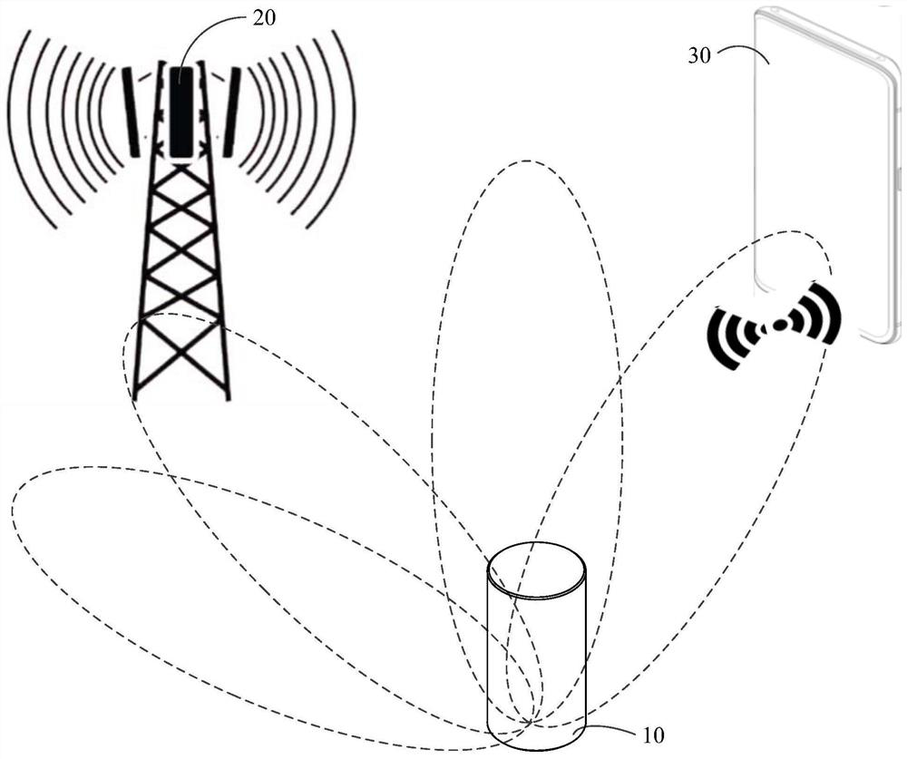
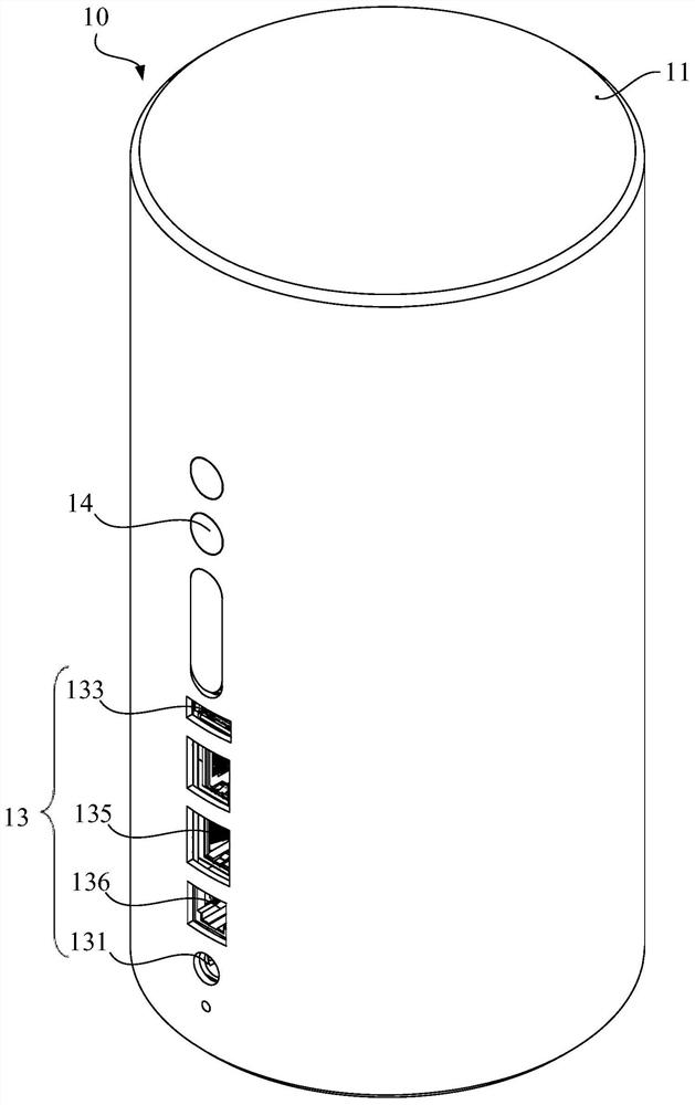
[0043]Seefigure 1 , Which shows a schematic diagram of the composition structure of a network system architecture provided by an embodiment of the present application. The customer premises equipment 10 is used to implement a network access function, which can convert the operator's public network WAN to the user's home local area network LAN. According to the current Internet broadband access methods, it can be divided into FTTH (...


PUM


Abstract

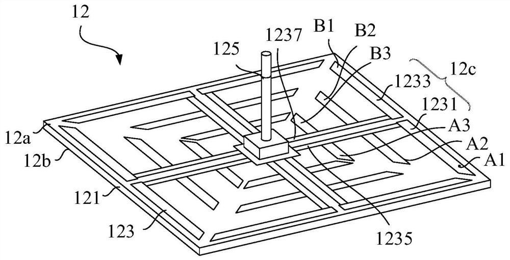
The invention relates to an antenna module and client front-end equipment. The antenna module comprises a substrate and an antenna, wherein the substrate has a first surface and a second surface opposite to each other, the antenna is arranged on the first surface and comprises more than three radiation units in rotational symmetry, the included angles between the adjacent radiation units are equal, each radiation unit comprises a first radiation group and a second radiation group which are in mirror symmetry, the first radiation group at least comprises a first radiation arm and a second radiation arm which are arranged at an interval, the length of the first radiation arm is greater than that of the second radiation arm, the second radiation group at least comprises a third radiation armand a fourth radiation arm which are arranged at an interval, the third radiation arm is arranged corresponding to the first radiation arm and used for radiating a first frequency band signal, and thefourth radiation arm is arranged corresponding to the second radiation arm and used for radiating a second frequency band signal. When the antenna module is used as a transmitting antenna, the characteristic of multi-band low directivity coefficient can be obtained, the gain of the transmitting antenna can be reduced, and the requirements of regional laws and regulations are met.

Description

Technical field[0001]This application relates to the field of antenna technology, in particular to an antenna module and customer front equipment.Background technique[0002]Customer Premise Equipment (CPE) is a mobile signal access device used to receive mobile signals and forward them with wireless WIFI signals. It is also a device that converts 4G or 5G signals into WiFi signals. Customer front-end equipment is generally placed indoors and can support multiple terminal devices (such as mobile phones, tablet computers, etc.) to access the network at the same time.[0003]The transmitting antennas of current customer front-end equipment are evolving towards high efficiency and high gain. The increase of the transmitting antenna gain can increase the coverage of the antenna signal, but the regional regulations generally have clear restrictions on the gain of the transmitting antenna. The gain of the transmitting antenna is prone to the problem that the gain of the transmitting antenna e...

Claims


Application Information

Patent Timeline
Patent Type & Authority Applications(China)
IPC IPC(8): H01Q1/38H01Q5/28H01Q5/307H01Q9/16H01Q1/22
CPCH01Q1/38H01Q5/28H01Q5/307H01Q9/16H01Q1/22
Inventor 陈志
Owner GUANGDONG OPPO MOBILE TELECOMM CORP LTD
Learn More