
Radio Frequency Inductively Coupled Plasma Superimposed Broadband Bandpass Frequency Selective Surface Structure

A technology of frequency selective surface and inductive coupling, which is applied in the field of active stealth, can solve the problems that the multi-frequency passband/stopband cannot be adjusted, and achieve the effect of increasing the range of incident angle, reducing reflection, and reducing insertion loss

Active Publication Date: 2022-02-01
AIR FORCE UNIV PLA
View PDF12 Cites 0 Cited by
  • Summary
  • Abstract
  • Description
  • Claims
  • Application Information

AI Technical Summary

Problems solved by technology

[0003] The purpose of the embodiments of the present invention is to provide a radio frequency inductively coupled plasma superimposed broadband bandpass frequency selective surface structure to solve the problem that the existing radome absorbing structure cannot realize multi-frequency passband / stopband adjustable

Method used


Image

  • Radio Frequency Inductively Coupled Plasma Superimposed Broadband Bandpass Frequency Selective Surface Structure
  • Radio Frequency Inductively Coupled Plasma Superimposed Broadband Bandpass Frequency Selective Surface Structure
  • Radio Frequency Inductively Coupled Plasma Superimposed Broadband Bandpass Frequency Selective Surface Structure

Examples


Embodiment Construction

[0033] The following will clearly and completely describe the technical solutions in the embodiments of the present invention with reference to the accompanying drawings in the embodiments of the present invention. Obviously, the described embodiments are only some, not all, embodiments of the present invention. Based on the embodiments of the present invention, all other embodiments obtained by persons of ordinary skill in the art without making creative efforts belong to the protection scope of the present invention.

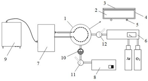
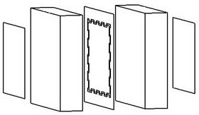
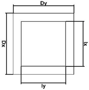
[0034] An embodiment of the present invention provides a radio frequency inductively coupled plasma superimposed broadband bandpass frequency selective surface structure, such as figure 1 As shown, it includes a plasma coupling frequency selective surface structure 1, and the plasma coupling frequency selective surface structure 1 includes a radio frequency inductively coupled plasma source 2, a broadband bandpass frequency selective surface 3 and a closed wave...


PUM


Abstract

The invention discloses a radio frequency inductively coupled plasma superimposed broadband bandpass frequency selective surface structure, comprising a plasma coupling frequency selective surface structure, the plasma coupling frequency selective surface structure comprising a radio frequency inductively coupled plasma source, a broadband passband frequency selective surface and a closed wave-transmitting dielectric cavity, wherein the radio frequency inductively coupled plasma source is placed in the closed wave-transmitting dielectric cavity, the broadband passband frequency selective surface is fixed above the closed wave-transmitting dielectric cavity, and the incident electromagnetic wave is incident to the broadband passband frequency On the selection surface; the broadband passband frequency selection surface is formed by arranging the broadband passband frequency selection units periodically along the X axis and the Y axis respectively, and the broadband passband frequency selection unit consists of a first metal layer, a first dielectric layer, and a second metal layer. layer, the second dielectric layer, and the third metal layer are stacked sequentially from top to bottom. The transmission of electromagnetic waves in a specific frequency band is realized through the resonance between the broadband passband frequency selection units arranged periodically.

Description

technical field [0001] The invention belongs to the technical field of active stealth and relates to a radio frequency inductively coupled plasma superimposed broadband bandpass frequency selective surface structure. Background technique [0002] The radome is used to protect the aerodynamic performance of the aircraft and the working environment of the radar antenna, but due to the wave-transparent properties of the radome, the antenna system is exposed to the head area of ​​the aircraft, forming a strong scattering area, which seriously reduces the survivability and Combat effectiveness. At present, the frequency selective surface is mainly used in the design of the radome. According to the frequency selective characteristics of the frequency selective surface, the passband of the frequency selective surface is designed to the work of the aircraft antenna without changing the material and wall structure of the radome. In the frequency band, it realizes the function of hig...

Claims


Application Information

Patent Timeline
Patent Type & Authority Patents(China)
IPC IPC(8): H01Q15/00
CPCH01Q15/0026
Inventor 魏小龙徐浩军韩欣珉武欣林茂
Owner AIR FORCE UNIV PLA
Learn More