Charge discharge circuit, converter, centrifugal unit and electric appliance
A technology of charge discharge and converter, which is applied in the field of converters, can solve the problems of increased safety hazards, waste of residual charge, high equipment cabinets, etc., and achieve the effect of increasing safety performance and reducing temperature
- Summary
- Abstract
- Description
- Claims
- Application Information
AI Technical Summary
Problems solved by technology
Method used
Image

Examples
Embodiment Construction
[0037]In order to make the purpose, technical solutions, and advantages of the present application clearer, the technical solutions of the present application will be described in detail below. Obviously, the described embodiments are only a part of the embodiments of the present application, rather than all the embodiments. Based on the embodiments in this application, all other implementations obtained by a person of ordinary skill in the art without creative work shall fall within the scope of protection of this application.
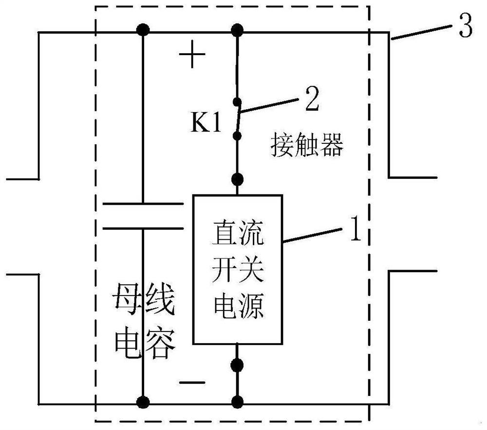
[0038]figure 1 This is a schematic diagram of the structure of a charge bleeder circuit provided by an embodiment of this application, such asfigure 1 As shown, the charge discharge circuit includes:
[0039]Switching power supply 1 and contactor 2 connected in series with the switching power supply;
[0040]The switching power supply 1 and the contactor 2 are connected in parallel on both ends of the capacitor of the bus 3 to be discharged.
[0041]In some embodiments...
PUM
 Abstract
Description
Claims
Application Information
 - R&D
- Intellectual Property
- Life Sciences
- Materials
- Tech Scout
- Unparalleled Data Quality
- Higher Quality Content
- 60% Fewer Hallucinations
Browse by: Latest US Patents, China's latest patents, Technical Efficacy Thesaurus, Application Domain, Technology Topic, Popular Technical Reports.
© 2025 PatSnap. All rights reserved.Legal|Privacy policy|Modern Slavery Act Transparency Statement|Sitemap|About US| Contact US: help@patsnap.com