Automatic assembling equipment and assembling method for gear assembly

An automatic assembly and gear set technology, which is applied in the direction of assembly machines, metal processing equipment, manufacturing tools, etc., can solve the problems of increasing installation difficulty, gear sets cannot be installed stably, and adding steps for zero adjustment, so as to avoid steric hindrance , reduce the impact, increase the effect of efficiency

Active Publication Date: 2021-03-02
宁波市海曙必伟工业自动化有限公司
View PDF12 Cites 3 Cited by
  • Summary
  • Abstract
  • Description
  • Claims
  • Application Information

AI Technical Summary

Problems solved by technology

[0003] In the prior art, the gear set cannot be installed stably. Taking the above gear set as an example, in the prior art, most of the gear sets are installed in the vertical direction one by one, but steric resistance is easily generated between individual gears. It increases the difficulty of installation, and when cutting the gears one by one, it is easy to drive the character wheel system to rotate, so that the pointer of the character wheel system is not zero, thus increasing the steps of zero adjustment

Method used


Image

  • Automatic assembling equipment and assembling method for gear assembly
  • Automatic assembling equipment and assembling method for gear assembly
  • Automatic assembling equipment and assembling method for gear assembly

Examples


Embodiment 1

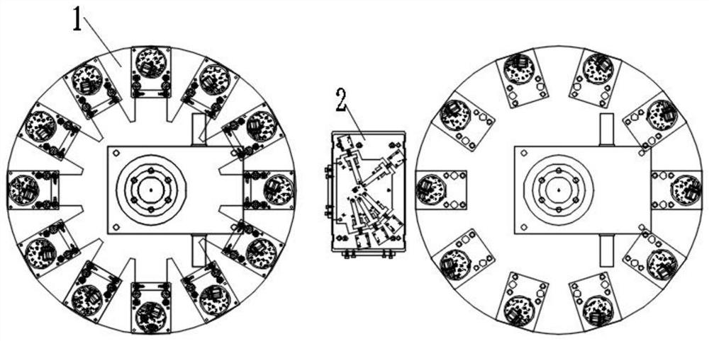
[0043] Embodiment 1: refer to figure 2, an automatic assembly equipment for gear assemblies. The gear set pre-installation device 1 is arranged on one side of the gear set assembly device 2. The gear set pre-installation device 1 is a rotating disk with a ring structure, and the rotating disk is driven by a motor. Twelve stations are arranged on the disc, including installation stations and positioning stations for ten gears in the gear train. The installation station of the gear adopts the method of vibrating plate and conveyor belt. The gear moves to the end of the conveyor belt. After pneumatic clamping, the gear is transferred to the rotating disk. The pneumatic clamping and positioning station make the gear accurately placed on the rotating disk. superior.

[0044] After the processing of the gear set pre-installation device 1, ten gears in the gear set are placed on the rotating disk, and the ten gears are separated from each other. Some of the gears are moving gears, ...

Embodiment 2

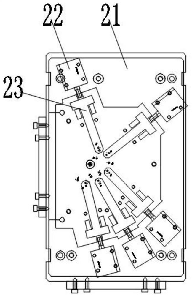
[0054] Embodiment 2: Combining with the basis of Embodiment 1, the difference lies in that in this embodiment, the gear set assembly device 2 is integrated with the clamping device group, that is, the clamping device is provided with a slide rail, and the corresponding clamping gear of the moving gear The head is slidingly connected with the slide rail, and the driving device 22 on the gear assembly device drives the clamping head to move along the slide rail.

[0055] The steps of the automatic assembly method of the gear assembly in this embodiment are as follows:

[0056] S1. The gear set pre-installation device 1 is used to combine the gears into a gear set according to the timing relationship, and the gears in the gear set are in a disengaged state;

[0057] S2. The whole disengaged gear set is clamped by the clamping device, and the clamping head in the clamping device is driven by the driving device 22 to drive the moving gear in the horizontal direction, so that the ge...

Embodiment 3

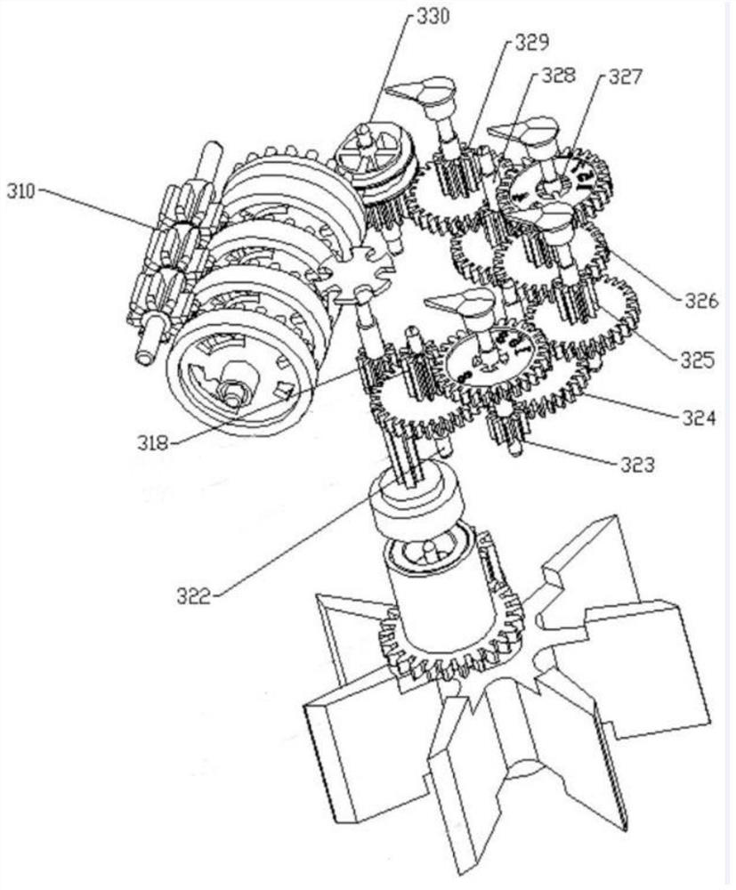
[0064] This embodiment is different from Embodiment 1 in that each gear in the gear set in this embodiment is a moving gear, that is, the moving gears are divided into two groups, the first gear 322, the second gear 323, the fourth gear 325, The sixth gear 327 and the eighth gear 329 form the first group, and the second sun gear 218 , the third gear 324 , the fifth gear 326 , the seventh gear 328 and the worm gear 330 form the second group. When the gear set assembly device 2 assembles the gear sets in the horizontal direction, the driving device 22 drives the first set of movable gears and the second set of movable gears to move toward each other until the entire gear set is meshed.

[0065] In some examples, the second sun gear 318, first gear 322, second gear 323, and third gear 324 are grouped into a first group, and the fourth gear 325, fifth gear 326, and sixth gear 327 are grouped into a second group. Two groups, the seventh gear 328, the eighth gear 329 and the worm ge...


PUM


Abstract

The invention discloses automatic assembling equipment for a gear assembly, and belongs to the field of gear assembly mounting. The equipment comprises gear sets, a gear set pre-mounting device, a gear set assembling device and a clamping device, wherein a plurality of gears in each gear set are movable gears; the gear set pre-mounting device is used for combining the gears into the gear sets in adisengaged state; the gear set assembling device pushes the movable gears in each gear set to enable the gears to be in meshing transmission; and the clamping device is used for moving in and movingout the gear sets on the gear set assembling device. By arranging the gear set assembling device, the gear sets in the disengaged state are connected in a meshed mode, the problem of steric hindrancecaused by the gear sets in the vertical mounting process is solved, and the gears are prevented from being damaged in the assembling process; and moreover, the meshed gear sets are small in form fluctuation in the moving process, reading deviation of a character wheel system is not likely to be caused, and the mounting stability of the gear sets is ensured.

Description

technical field [0001] The invention relates to the field of gear assembly installation, in particular to an automatic assembly device for gear assemblies and an assembly method thereof. Background technique [0002] In the patent document that the authorized announcement number is CN210005051U, a kind of rotor type water meter is disclosed, such as figure 1 As shown: it includes a gear box, an impeller box and the impeller in it, and the counting mechanism includes a gear system, a pointer and a character wheel system 310. It is characterized in that the gear system includes a transition gear, a second central gear 318, and a magnetic element coupled The first transmission shaft and the second transmission shaft, the stepped first gear shaft 322, the second gear shaft 323, the third gear shaft 324, the fourth gear shaft 325, the fifth gear shaft 326, the sixth gear The shaft 327, the seventh gear shaft 328, the eighth gear shaft 329 and the worm gear 330, the worm gear 330...

Claims


Application Information

Patent Timeline
Patent Type & Authority Applications(China)
IPC IPC(8): B23P21/00
CPCB23P21/00Y02E10/20
Inventor 毛毕伟
Owner 宁波市海曙必伟工业自动化有限公司
Why Eureka
Try Eureka