Cooperative air suction type liquid rocket engine propellant supply system

A liquid rocket and supply system technology, applied in the field of aerospace power, can solve the problems of huge structural mass, burden, insufficient to drive propellant supply, etc., and achieve the effect of simple internal structure, high energy utilization rate, and avoiding hydrogen embrittlement effect.

Active Publication Date: 2021-03-02
PLA PEOPLES LIBERATION ARMY OF CHINA STRATEGIC SUPPORT FORCE AEROSPACE ENG UNIV
View PDF16 Cites 4 Cited by
  • Summary
  • Abstract
  • Description
  • Claims
  • Application Information

AI Technical Summary

Problems solved by technology

However, the hydrogen-oxygen rocket engine in my country started relatively late, and its thrust and specific impulse are relatively low compared with foreign countries. How to improve the performance of the hydrogen-oxygen rocket engine is the focus of research in the field of aerospace power in my country.
[0003] Traditional liquid rocket engines can be divided into pump type and squeeze type according to their propellant supply methods. However, there are some problems in the structure of these two methods: taking the pump type as an example, a large number of valves, pumps, etc. The use of the original parts needs to be driven by a power source, which creates a burden on the power supply subsystem of the rocket. The limited power supply capacity is not enough to drive the supply of propellant, and "small engines" such as gas generators and fuel start-up tanks are needed to realize the supply of propellant, resulting in The pump-pressed liquid rocket engine has a complex structure and is prone to failure
Although the squeeze-type liquid rocket engine has a simple structure, it needs to carry high-pressure gas cylinders and other components, resulting in a huge structural mass. It is generally suitable for propulsion systems with small thrust and low total impulse requirements, or for orbital attitude control engines for satellites.
These same propellant supply system problems exist for hydrogen-oxygen engines

Method used


Image

  • Cooperative air suction type liquid rocket engine propellant supply system
  • Cooperative air suction type liquid rocket engine propellant supply system
  • Cooperative air suction type liquid rocket engine propellant supply system

Examples


Embodiment Construction

[0041] The present invention will be further described in detail below in conjunction with the accompanying drawings and specific preferred embodiments.

[0042] In the description of the present invention, it should be understood that the orientations or positional relationships indicated by the terms "left side", "right side", "upper", "lower" are based on the orientations or positional relationships shown in the accompanying drawings, and are only For the purpose of describing the present invention and simplifying the description, rather than indicating or implying that the device or element referred to must have a specific orientation, be constructed and operate in a specific orientation, "first", "second" and the like do not represent components importance, and therefore should not be construed as limiting the invention. The specific dimensions used in this embodiment are only for illustrating the technical solution, and do not limit the protection scope of the present in...


PUM


Abstract

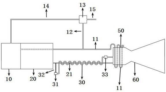
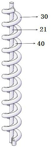
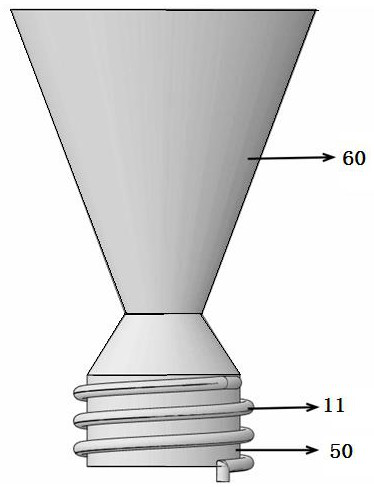
The invention discloses a cooperative air suction type liquid rocket engine propellant supply system which comprises a liquid oxygen storage tank, a liquid hydrogen storage tank, a liquid oxygen pipeline, a liquid hydrogen pipeline, a high-temperature incoming flow air pipeline, a helium pipeline and a rocket thrust chamber. A rocket belly is formed between the liquid hydrogen storage tank and therocket thrust chamber; the liquid hydrogen pipeline is positioned at the rocket belly and is linearly arranged; the high-temperature incoming flow air pipeline and the helium pipeline are wound at the outer side of the liquid hydrogen pipeline in parallel, and the helium pipeline is located between the two pipelines; a telescopic arm with a telescopic length is mounted on the side wall of an airinlet; when the telescopic arm is lengthened, the air inlet is pushed out from the rocket belly to realize an air suction working mode; and when the length of the telescopic arm is shortened, the airinlet is stored in the rocket belly, and a pure rocket working mode is achieved. According to the cooperative air suction type liquid rocket engine propellant supply system, oxygen in the atmosphere can be utilized, the layout of internal pipelines of a traditional liquid rocket engine is optimized, the liquid rocket engine has the high specific impulse and the large thrust-weight ratio, and therefore the launching cost is reduced.

Description

technical field [0001] The invention relates to the field of aerospace power, in particular to a propellant supply system for a cooperative air-breathing liquid rocket engine. Background technique [0002] Among all kinds of aerospace power devices, liquid rocket engines are widely used because of their large specific impulse and easy control. The hydrogen-oxygen rocket engine is a liquid rocket engine that uses liquid oxygen as the oxidant and liquid hydrogen as the combustion agent. Liquid hydrogen and liquid oxygen are the only combination of liquid propellants with a specific impulse exceeding 400s. Due to their high specific impulse The advantages, can greatly reduce the rocket take-off weight, is widely used in launch vehicles. However, the hydrogen-oxygen rocket engine in my country started late, and compared with foreign countries, its thrust and specific impulse are relatively low. How to improve the performance of the hydrogen-oxygen rocket engine is the focus of ...

Claims


Application Information

Patent Timeline
Patent Type & Authority Applications(China)
IPC IPC(8): F02K9/44F02K9/60F02K9/62F02K9/78
CPCF02K9/44F02K9/60F02K9/62F02K9/78
Inventor 周思引朱浩然陈飞宇邓志刚白莹聂万胜
Owner PLA PEOPLES LIBERATION ARMY OF CHINA STRATEGIC SUPPORT FORCE AEROSPACE ENG UNIV
Why Eureka
Try Eureka