Self-service hairdressing machine
A technology of hair clippers and roll film machines, applied in the field of self-service hairdressers, which can solve the problems of continuous start-up noise, low degree of self-service, manual cleaning, etc., and achieve the effect of convenient use, high degree of self-service, and avoiding safety accidents
- Summary
- Abstract
- Description
- Claims
- Application Information
AI Technical Summary
Problems solved by technology
Method used
Image
Examples
Embodiment 1
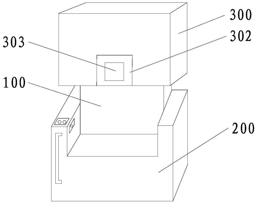
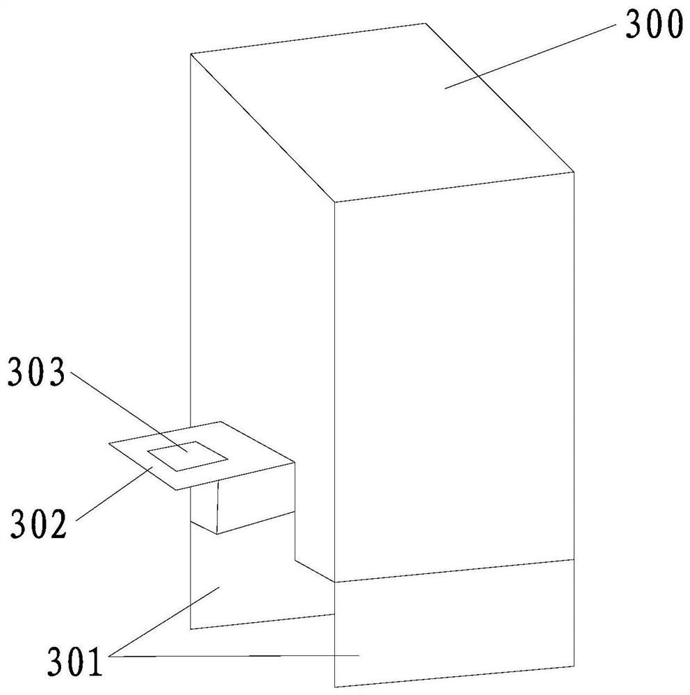
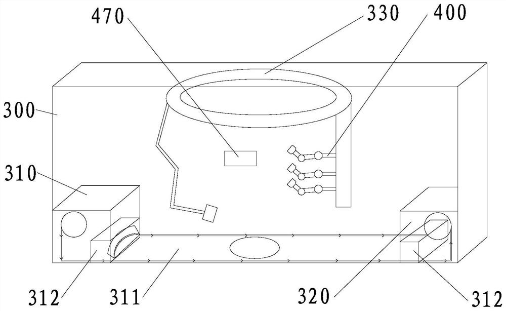
[0059] Such as Figure 1-Figure 10 As shown, the present embodiment provides a self-service hair extension machine, including a control module (not shown in the figure), a stand 100, a seat 200 fixedly connected to the stand 100, a vertical sliding connection to the stand 100 and The main compartment 300 located directly above the seat 200 and the lifting device (not shown) for driving the main compartment 300 to slide relative to the stand 100, wherein the control module can be arranged on the stand 100 or the seat 200, It is a conventional module, which can be purchased directly from the market and set according to actual functional requirements. The lifting device is also a conventional device, such as a hydraulic lifting device or an electric screw lifting device, etc. These are not the focus of this embodiment. No more details here. Preferably, the self-service hair extension machine provided in this embodiment also includes a user terminal wirelessly connected to the co...
Embodiment 2
[0084] This embodiment provides a self-service hairdresser or a combing and cutting assembly for a self-help Embodiment A dual-motor-driven clamping mechanism and scissors mechanism is replaced by a motor-driven clamping mechanism and scissors mechanism.
[0085] Specifically, such as Figure 11-Figure 12As shown, in this embodiment, the clamping mechanism includes a shaft 443 fixedly connected to the comb body, a first clamping rod 444 and a second clamping rod 445 whose shafts are respectively rotatably connected to the shaft 443, A clamping motor (not shown) that drives the first clamping rod 444 and the second clamping rod 445 action, a rotating disk 446 that is fixedly connected to the output shaft of the clamping motor and two fixedly connected on the rotating disk 446 And take the output shaft of the clamping motor as the center of the drive rod 447 that is symmetrically arranged. Similarly, one end of the first clamping rod 444 and the second clamping rod 445 all exte...
Embodiment 3
[0088] Such as Figure 13 shown, and refer to Figure 1-Figure 12 The difference between this embodiment and Embodiment 1 or Embodiment 2 is that the combing and shearing assembly 400 includes an annular track 330 fixedly connected to the upper part of the inner chamber of the main compartment 300. When in use, the head of the person is positioned Below the inner ring of the ring track 330, the ring track 330 is slidably connected with a suction clamp device 480, a scraper device 430 and a support plate 331. Specifically, the ring track 330 is provided with three coaxially arranged ring grooves, and the three ring grooves The suction clamp device 480, the scraper device 430 and the support plate 331 are respectively matched one by one, so that the suction clamp device 480, the scraper device 430 and the support plate 331 can slide independently without interference.
[0089] The difference between the structure of the suction clamping device 480 and the front suction clamping...
PUM
 Abstract
Description
Claims
Application Information
 - R&D
- Intellectual Property
- Life Sciences
- Materials
- Tech Scout
- Unparalleled Data Quality
- Higher Quality Content
- 60% Fewer Hallucinations
Browse by: Latest US Patents, China's latest patents, Technical Efficacy Thesaurus, Application Domain, Technology Topic, Popular Technical Reports.
© 2025 PatSnap. All rights reserved.Legal|Privacy policy|Modern Slavery Act Transparency Statement|Sitemap|About US| Contact US: help@patsnap.com


