X-ray pen beam scanning intensity modulation treatment linear accelerator device

A linear accelerator and intensity-modulated therapy technology, which is applied in linear accelerator, X-ray/γ-ray/particle irradiation therapy, treatment, etc., can solve the problems of high manufacturing cost, long treatment time, difficult and non-coplanar field irradiation, etc.

Active Publication Date: 2021-03-05
胡逸民
View PDF10 Cites 0 Cited by
  • Summary
  • Abstract
  • Description
  • Claims
  • Application Information

AI Technical Summary

Problems solved by technology

The advantages of the first-generation C-arm structure accelerator treatment machine and the second-generation ring structure second-generation treatment machine are mainly reflected in: large-field intensity-modulated irradiation can be realized; field position, shape and dose verification can be performed, but also It has the following disadvantages: it is difficult to achieve non-coplanar field irradiation; it is difficult to design non-coplanar field irradiation plan; the dose rate of the target area is relatively low; it is difficult to use the time dose fractionation factor; the treatment time is relatively long
However, the manufacturing cost of MLC is very high (accounting for about 1 / 4 to 1 / 3 of the total cost of the accelerator), and because the assembly between the blades needs to be tightly matched, the blades need to move continuously when the intensity is adjusted, so the motor that drives the blades moves Very fragile and expensive to repair

Method used


Image

  • X-ray pen beam scanning intensity modulation treatment linear accelerator device
  • X-ray pen beam scanning intensity modulation treatment linear accelerator device

Examples


Embodiment Construction

[0031] Reference will now be made in detail to various embodiments of the invention, examples of which are illustrated in the accompanying drawings and described below. While the invention will be described in conjunction with exemplary embodiments, it will be understood that present description is not intended to limit the invention to those exemplary embodiments. On the contrary, the invention is intended to cover not only the exemplary embodiments but also various alternatives, modifications, equivalents and other alternatives, modifications, equivalents and others, which may be included within the spirit and scope of the invention as defined by the appended claims. implementation plan.

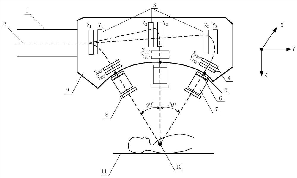
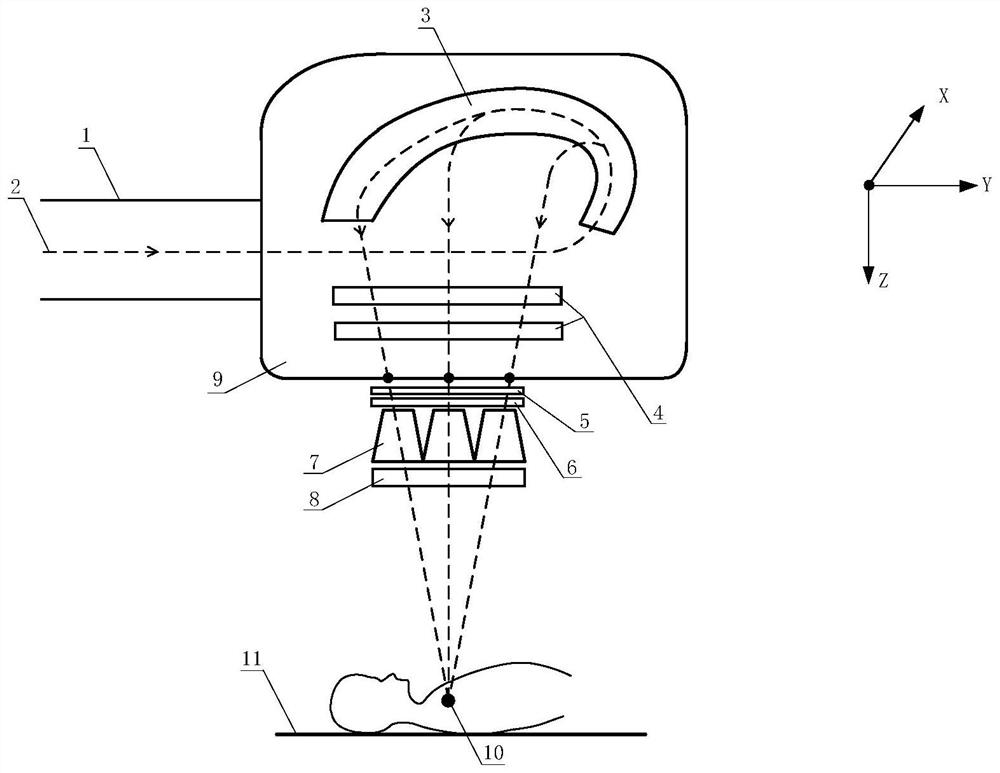
[0032] The following will refer to the attached figure 1 with 2 Exemplary embodiments of the present invention are described in detail.

[0033] refer to figure 1 with figure 2 , as shown in the three-dimensional coordinate system in the figure, figure 1 with figure 2It is a Y-...


PUM


Abstract

The invention relates to an X-ray pencil beam scanning intensity modulation treatment linear accelerator device. The device can generate an X-ray scanning pencil beam, the device comprises a standingwave accelerating tube with a grid-control electron gun, a vacuum electromagnetic deflection chamber and an X-ray planar distribution target, a Y-Z plane electron deflection magnet and an X-Y plane electron deflection magnet which correspond to each other are arranged in the vacuum electromagnetic deflection chamber, the Y-Z plane electron deflection magnet and the X-Y plane electron deflection magnet are respectively used for Y-Z plane electron beam magnetic deflection and X-Y plane electron beam magnetic deflection, the electron beam accelerated to have the preset energy is generated in thestanding wave accelerating tube, leaves the standing wave accelerating tube and then enters the vacuum electromagnetic deflection chamber to be subjected to Y-Z plane electromagnetic deflection and X-Y plane electromagnetic deflection in sequence, the electron beam entering the vacuum electromagnetic deflection chamber leaves the vacuum electromagnetic deflection chamber according to a preset direction after being deflected, and hits a preset position of a corresponding X-ray plane distribution target to generate the X-ray pencil beam, and the X-ray pencil beam enters a honeycomb collimator arranged at the lower end according to a preset direction to form the X-ray pencil beam for intensity modulation treatment.

Description

technical field [0001] The invention relates to an X-ray pencil beam scanning intensity modulation therapy linear accelerator device, which can be used for intensity modulation conformal radiation therapy in tumor radiation therapy. Background technique [0002] Cancer has become the main killer that endangers human health, and it is one of the main diseases that threaten the health of our country. Radiation therapy is still one of the main means of treating malignant tumors, and about 65% to 70% of tumor patients need to receive radiation therapy to varying degrees. [0003] Before the 1980s, two-dimensional radiation therapy was the main technology for tumor radiation therapy. After entering the 1990s, China's tumor radiation therapy technology has entered the era of 3D radiation therapy from the era of 2D radiation therapy, and three-dimensional conformal (3D-CRT) and intensity-modulated radiation therapy (IMRT) treatment technologies have appeared; stereotaxic Treatmen...

Claims


Application Information

Patent Timeline
IPC IPC(8): A61N5/10H05H9/04H05H7/22
CPCA61N5/1045A61N5/103A61N5/1077H05H9/04H05H7/22A61N2005/1089A61N2005/1092
Inventor 胡逸民
Owner 胡逸民
Why Eureka
Try Eureka