Q-switched holmium laser

A holmium laser and laser technology, applied in the field of Q-switched holmium lasers, can solve the problems of increasing resonator loss, loss, and cluttered pulse signals, and achieve the effect of compact structure and stable Q-switched pulse output

Inactive Publication Date: 2021-03-05
FUJIAN INST OF RES ON THE STRUCTURE OF MATTER CHINESE ACAD OF SCI
View PDF8 Cites 2 Cited by
  • Summary
  • Abstract
  • Description
  • Claims
  • Application Information

AI Technical Summary

Problems solved by technology

However, the Tm-doped part and the Ho-doped part in the bonding gain medium interact with each other. The Tm-doped part not only provides the Tm laser for pumping the Ho-doped part, but also acts as a saturable absorber for the Ho laser. The Ho-doped part consumes the Tm in the cavity. The laser energy is also equivalent to the saturated absorber of the Tm laser, which affects the time stability of the Tm pump light in the cavity
[0003] The above situation has caused the Tm / Ho bonding laser to have a messy pulse signal in the free running state, and it is impossible to use the traditional active Q-switching method (that is, inserting acousto-optic or electro-optic in the resonant cavity of the Tm / Ho bonding laser) modulation device) to generate a stable Q-switched pulse output
On the other hand, the traditional passive Q-switching method of directly inserting a saturable absorber in the resonator is also difficult to achieve laser output on the Tm / Ho bonded laser, because the introduction of the saturable absorber increases the loss of the resonator, which is harmful to Ho lasers, especially the Tm lasers pumped in the cavity with Ho-doped parts, cause loss and cannot form laser oscillation output.
That is to say, because there are both Tm laser and Ho laser in the cavity, the Q-switching element weakens the Tm laser, so that the Ho laser cannot be fully excited by the Tm laser, and cannot form an effective Ho laser output.

Method used


Image

  • Q-switched holmium laser
  • Q-switched holmium laser
  • Q-switched holmium laser

Examples


Embodiment 1

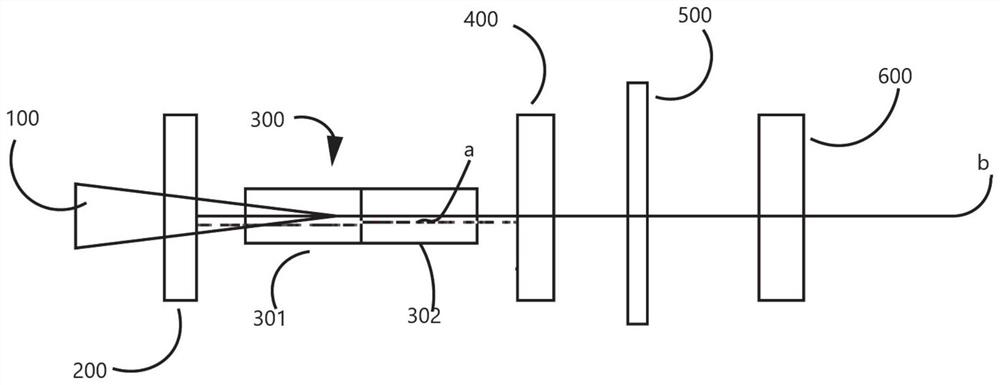
[0089] figure 1 For the structural representation of the Q-switched holmium laser provided by this embodiment, below in conjunction with figure 1 This embodiment will be described.

[0090] Such as figure 1 As shown, the Q-switched holmium laser sequentially includes a pump source 100 , a front cavity mirror 200 , a Tm / Ho composite gain medium 300 , a filter device 400 , a Q-switched element 500 and a rear cavity mirror 600 along the optical path. The Tm / Ho composite gain medium 300 includes a Tm-doped part 301 and a Ho-doped part 302, and is wrapped by indium foil and fixed in a cooling copper block (not shown in the figure) with built-in micro-channels. The Q-switching element 500 is interposed between the filter device 400 and the rear cavity mirror 600 .

[0091] The rear end surface of the front cavity mirror 200 is coated with a first reflective film with a reflectivity greater than 99.7% to the Tm laser a, and the front surface of the transparent insulator of the fil...

Embodiment 2

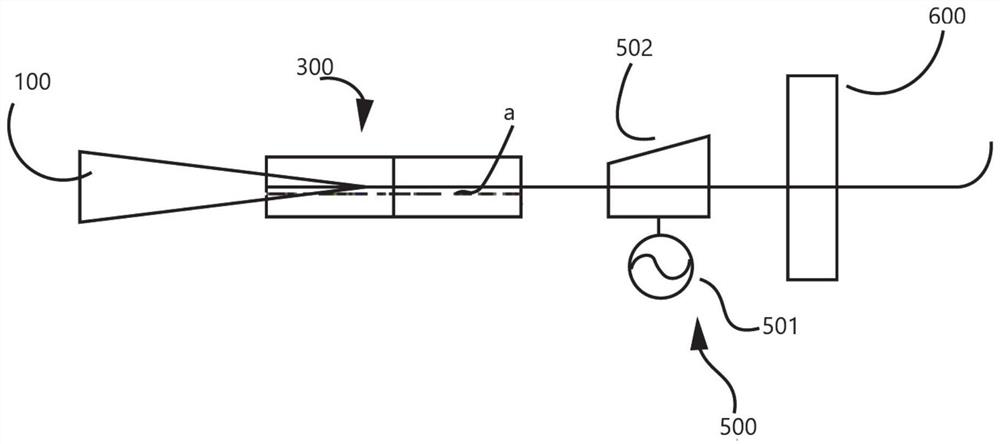
[0100] figure 2 For the structural representation of the Q-switched holmium laser provided by this embodiment, below in conjunction with figure 2 This embodiment will be described.

[0101] In specific implementation, such as figure 2 As shown, the functional film layer (i.e. the first reflective film) of the filter device 400 in Embodiment 1 is plated on the rear end surface of the composite gain medium 300, and the functional film layer (the first reflective film) of the front cavity mirror 200 in Embodiment 1 is coated A reflective film and a second reflective film) are plated on the front face of the composite gain medium 300, and then the composite gain medium 300 becomes a resonant cavity (i.e., a filter resonator) that confines the Tm laser a, and the composite gain medium 300 also becomes the laser resonant cavity At one end, the second reflective film is coated on the front end of the rear cavity mirror 600, and the rear cavity mirror 600 becomes the other end of...

Embodiment 3

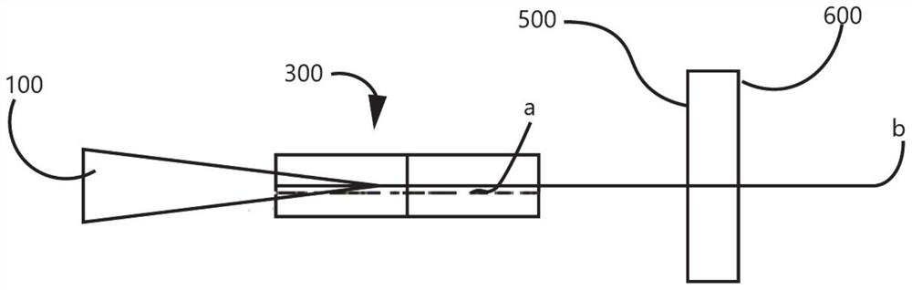
[0103] image 3 For the structural representation of the Q-switched holmium laser provided by this embodiment, below in conjunction with image 3 This embodiment will be described.

[0104] The Q-switching element 500 can be a saturable absorber or a saturable absorber based on a one-dimensional or two-dimensional material, and the MoSe 2 Uniformly coat the front end of the rear cavity mirror 600, and the front and rear end surfaces of the composite gain medium 300 act as the front cavity mirror and the filter device in Embodiment 1, respectively, and confine the Tm laser a in the composite gain medium 300 to the Ho-doped part Perform uniform pumping (similar to the composite gain medium in Example 2), and then realize pulsed Ho laser output. image 3 The structure is conducive to the figure 2 On the basis of the structure, the structure and size of the laser are further simplified, and the pulsed Ho laser output is realized under conventional LD ​​pumping.


PUM

PropertyMeasurementUnit
reflectanceaaaaaaaaaa

Abstract

The invention discloses a Q-switched holmium laser. The Q-switched holmium laser comprises a composite resonant cavity, a Tm/Ho composite gain medium, a Q-switched element and a pumping source; the composite resonant cavity comprises a laser resonant cavity and a filtering resonant cavity; the filtering resonant cavity and the Q-switched element are sequentially positioned in the laser resonant cavity along the light path direction; the Tm/Ho composite gain medium is located in the filtering resonant cavity; the pumping source is positioned outside the laser resonant cavity; wherein the filtering resonant cavity is used for separating Tm laser from Ho laser. The laser comprises a composite resonant cavity, the composite resonant cavity realizes separation of Tm laser and Ho laser, and theTm laser is confined in a filtering resonant cavity, so a Q-switched element only influences the Ho laser, and the Tm laser can effectively excite the Ho laser to form stable Q-switched pulse output.

Description

technical field [0001] The present application relates to a Q-switched holmium laser and the field of solid-state laser technology. Background technique [0002] In the existing all-solid-state holmium (Ho) laser implementation, compared to the bulky Tm laser pumping the Ho laser, the expensive 1.9 μm semiconductor laser LD pumps the Ho laser, and the complex structure of the Tm laser resonator pumps the Ho laser. Laser, Tm / Ho bonding laser is a compact, miniaturizable, economical and convenient way to realize Ho laser. It can directly use conventional LD ​​(wavelength 750nm~810nm) to efficiently realize room temperature Ho laser output. However, the Tm-doped part and the Ho-doped part in the bonding gain medium interact with each other. The Tm-doped part not only provides the Tm laser for pumping the Ho-doped part, but also acts as a saturable absorber for the Ho laser. The Ho-doped part consumes the Tm in the cavity. At the same time, the laser energy is equivalent to the...

Claims


Application Information

Patent Timeline
Patent Type & Authority Applications(China)
IPC IPC(8): H01S3/08H01S3/11H01S3/113H01S3/16
CPCH01S3/08H01S3/11H01S3/113H01S3/161
Inventor 黄海洲林文雄李锦辉邓晶葛燕翁文
Owner FUJIAN INST OF RES ON THE STRUCTURE OF MATTER CHINESE ACAD OF SCI
Why Eureka
Try Eureka