
Novel magnesium alloy plate material cable bridge

A technology of magnesium alloy plate and cable tray, applied in electrical components and other directions, can solve problems such as environmental pollution and poor corrosion resistance

Inactive Publication Date: 2021-03-05
泰州特邑斯金属制品科技有限公司
View PDF6 Cites 3 Cited by
  • Summary
  • Abstract
  • Description
  • Claims
  • Application Information

AI Technical Summary

Problems solved by technology

[0005] Aiming at the deficiencies of the prior art, the present invention provides a new type of cable tray made of magnesium alloy plate material, which solves the problem that the existing cable tray has poor corrosion resistance and many deficiencies still exist during use, and the traditional Bridge production requires galvanizing, and the galvanizing process has a large environmental pollution problem

Method used


Image

  • Novel magnesium alloy plate material cable bridge
  • Novel magnesium alloy plate material cable bridge

Examples


Embodiment 1

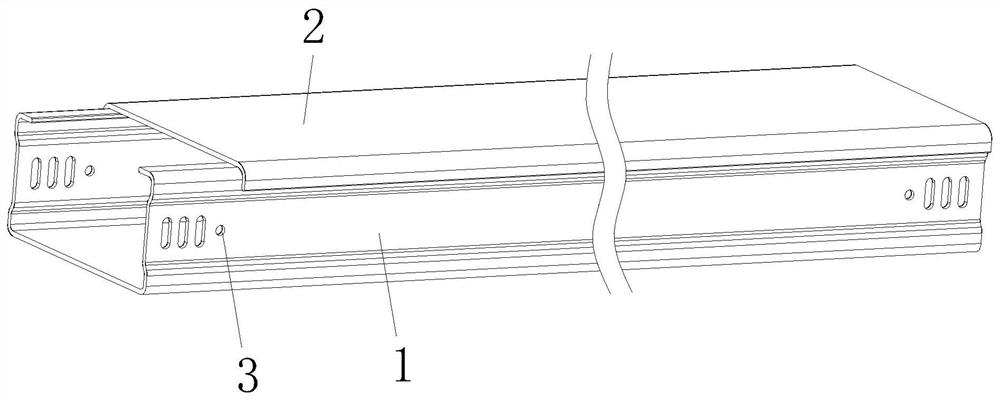
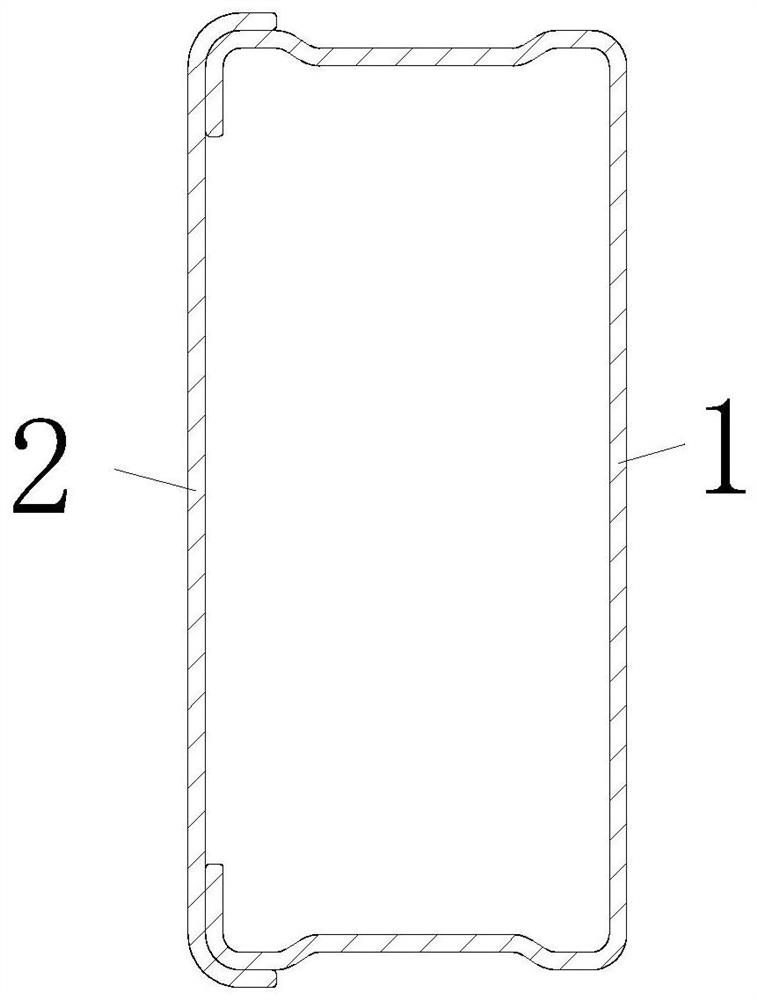
[0028] see Figure 1-2 As shown, the present invention provides the following technical solutions: a novel magnesium alloy plate material cable bridge, comprising a bridge tank box 1 and a bridge tank cover 2, the upper cover of the bridge tank box 1 is equipped with a bridge tank cover 2, the bridge tank box 1 There are connecting bolt holes 3 at both ends of the groove walls on both sides;

[0029] A kind of production method of novel magnesium alloy plate material cable bridge, comprises the following steps:

[0030] S1: Use the uncoiler to unroll the coiled magnesium alloy plate, and transport it to the leveler to level the magnesium alloy plate;

[0031] S2: The magnesium alloy plate after leveling in S1 is transported to the cutting device by a private feeder, cut according to the actual bridge size, and then transported to the punching device for punching, and the bolts at the end of the bridge are processed Holes, and finally the corners of the magnesium alloy sheet ...

Embodiment 2

[0046] see Figure 1-2 As shown, the present invention provides the following technical solutions: a new type of magnesium alloy plate material cable tray, according to the cable tray described in Embodiment 1, when it needs to be used in a fireproof environment, the bridge slot box 1 and the The surface of the bridge tank cover 2 is sprayed with fireproof powder coating. The fireproof coating has excellent flame retardant performance, strong heat insulation performance, excellent fire resistance performance, little environmental pollution, and the fireproof coating has strong adhesion to the bridge matrix and good comprehensive performance. ;Small smell, the fire retardant coating conforms to the standard of GB14907-2002 "General Technical Conditions of Fireproof Coatings for Steel Structures", and the fire resistance limit reaches 3h-3.5h.


PUM

PropertyMeasurementUnit
Fire resistanceaaaaaaaaaa

Abstract

The invention belongs to the technical field of cable bridges, and particularly relates to a novel magnesium alloy plate material cable bridge which comprises a bridge groove box and a bridge groove cover. The upper portion of the bridge groove box is covered with the bridge groove cover, and connecting bolt holes are formed in the two ends of the groove walls of the two sides of the bridge groovebox. The corrosion-resistant self-healing magnesium alloy plate is integrally formed by processing a magnesium alloy plate, has excellent processability under severe conditions, has excellent damageresistance, has better corrosion resistance compared with common galvanized and aluminum-zinc plated products, can replace stainless steel or aluminum to be used in some fields, has a corrosion-resistant self-healing effect on a cutting end face part. Compared with a galvanized corrosion product, the corrosion product of the zinc-aluminum-magnesium coating has the advantages of higher compactness,low conductivity, high adhesiveness, high dissolution resistance, decomposability and the like, has higher corrosion resistance, does not need galvanizing, is energy-saving and environment-friendly,reduces environmental pollution, and under normal processing and use conditions, the use temperature is not higher than 100 DEG C, so that corrosion perforation can be avoided within thirty years.

Description

technical field [0001] The invention relates to the technical field of cable bridges, in particular to a novel magnesium alloy plate material cable bridge. Background technique [0002] The cable tray is a commonly used support and protection device for laying cables, which protects and guides the cables laid in the cable tray. In the prior art, cable bridges mainly include steel bridges, aluminum alloy bridges, stainless steel bridges, glass steel bridges, etc., which are widely used in the market. Steel bridges, aluminum alloy bridges and stainless steel bridges all have good mechanical properties. performance. [0003] However, the existing cable bridges have poor corrosion resistance, and there are still many deficiencies in the use process, and the traditional production of bridges requires galvanizing, and the galvanizing process has a large environmental pollution. Contents of the invention [0004] (1) Solved technical problems [0005] Aiming at the deficiencie...

Claims


Application Information

Patent Timeline
IPC IPC(8): H02G3/04
CPCH02G3/0406H02G3/0418H02G3/0437H02G3/0456
Inventor 崔云磊
Owner 泰州特邑斯金属制品科技有限公司
Learn More