
Ultralow-temperature liquid nitrogen test box

A test chamber and ultra-low temperature technology, used in the field of test chambers, can solve problems such as inability to solve sealing problems, and achieve the effects of good frost resistance and high mechanical strength

Pending Publication Date: 2021-03-09
TIANJIN AEROSPACE RELIA TECH +1
View PDF0 Cites 0 Cited by
  • Summary
  • Abstract
  • Description
  • Claims
  • Application Information

AI Technical Summary

Problems solved by technology

However, the current test chamber cannot solve the sealing problem under ultra-low temperature conditions.

Method used


Image

  • Ultralow-temperature liquid nitrogen test box
  • Ultralow-temperature liquid nitrogen test box
  • Ultralow-temperature liquid nitrogen test box

Examples


Embodiment 1

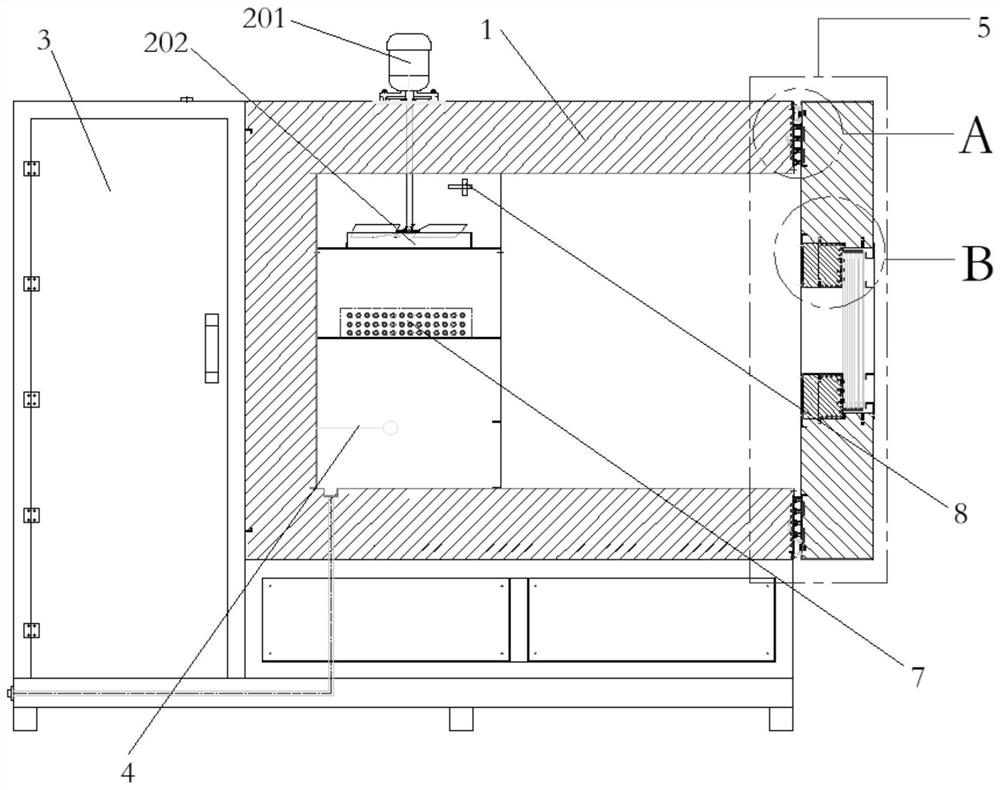
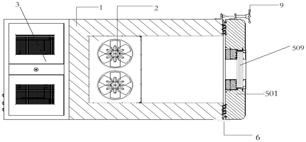
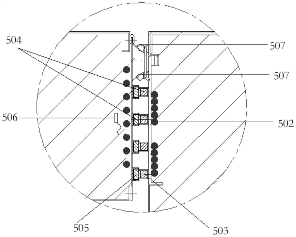
[0019] According to the above technical problems, the present invention provides an ultra-low temperature liquid nitrogen test chamber, including a test chamber body 1, an air circulation device 2, a control device 3, a liquid nitrogen spray device 4, a door sealing system 5, a hinge 6, and a heater 7 , a temperature sensor 8, a door lock 9, the control device 3 is arranged next to the test chamber body 1, and the test chamber body 1 is provided with a wind circulation device 2, and the wind circulation device 2 includes a motor 201 and a wind wheel 202. The motor 201 is fixedly mounted on the top of the test chamber body 1, the wind wheel 202 is connected to the output shaft of the motor 201, a temperature sensor 8 is arranged between the wind wheel 202 and the test chamber body 1, and the wind wheel 202 is below the A heater 7 is provided, and a liquid nitrogen spraying device 4 is provided below the heater 7, and the liquid nitrogen spraying device 4 is used for spraying unv...

Embodiment 2

[0028]Working principle: when the present invention is in use, the test box body 1 and the test box door 501 are made of strong heat-insulating materials, so that the test box body 1 maintains a stable low-temperature environment under the premise that the test box door is effectively sealed. The wind circulation device 2 is used to uniformly pass the air in the test chamber through the liquid nitrogen spray device 4 to realize the rapid cooling of the test chamber body 1, and the temperature sensor 8 device is used to collect the temperature parameters in the test chamber body 1, And the temperature parameter is transmitted to the control device 3, and the control device 3 is used to control the working state of the liquid nitrogen cooling system in combination with the temperature parameter and the preset temperature value. The sealing of the test box door 501 and the test box body 1 is completed by the door sealing system 5. The test box door 501 and the test box body 1 are ...


PUM


Abstract

The invention relates to an ultralow-temperature liquid nitrogen test box, which comprises a test box body, an air circulation device, a control device, a liquid nitrogen spraying device, a door sealing system, a hinge, a heater, a temperature sensor and a door lock; four sets of primary and secondary tanks are arranged on a door of the test box; glass fiber pipes are arranged in the primary and secondary tanks; the door can be closed and firmly pressed, so that low-temperature nitrogen in the box from can be prevented from directly contacting flexible silicone rubber used for sealing; in order to prevent the silicon rubber from embrittlement and inactivation at an extremely low temperature, heating wires are arranged around the door frame of the door, so that the silicon rubber is alwayskept at the optimal working temperature close to the normal temperature; and a glass observation window is arranged on the equipment door, the glass observation window is a coating film heating type multilayer hollow observation window, heating wires are arranged in the glass observation window, and therefore, water vapor can be effectively prevented from being condensed on the surface of the glass observation window when the equipment is at a low temperature; and glass fiber pipes and fluororubber sealing strips are used for sealing the periphery of the glass observation window to achieve overall sealing of glass.

Description

technical field [0001] The invention relates to a test box, in particular to an ultra-low temperature liquid nitrogen test box. Background technique [0002] The ultra-low temperature liquid nitrogen test chamber belongs to the type of test chamber with a high degree of difficulty. The main difficulty lies in that the lowest temperature of the test chamber can reach -180°C. Therefore, it is difficult to realize the door sealing device of the entire test chamber. It will become brittle, harden and seal failure at around -100°C. Therefore, for ultra-low temperature liquid nitrogen test chambers, it is necessary to find new sealing materials and new sealing methods to realize the sealing of liquid nitrogen. [0003] Whether the door seal of the ultra-low temperature liquid nitrogen test chamber is successfully developed is the foundation of whether this type of equipment can be successfully developed. When the liquid nitrogen test is carried out in the low temperature test cham...

Claims


Application Information

Patent Timeline
IPC IPC(8): B01L1/00B01L7/00
CPCB01L1/00B01L7/00
Inventor 倪丽蕊杨玉强王有杰薛志军王福
Owner TIANJIN AEROSPACE RELIA TECH
Learn More