

Board grinding device for PCB machining
A technology of PCB circuit boards and boards, which is applied in the direction of grinding drive devices, metal processing equipment, grinding machines, etc., can solve the problems that cannot be fully polished, debris is difficult to collect and remove, and affects grinding, so as to ensure cleanliness and normal operation. Improves sanding quality and removes effortlessly
- Summary
- Abstract
- Description
- Claims
- Application Information
AI Technical Summary
Problems solved by technology
Method used
Image

Examples
Embodiment 1
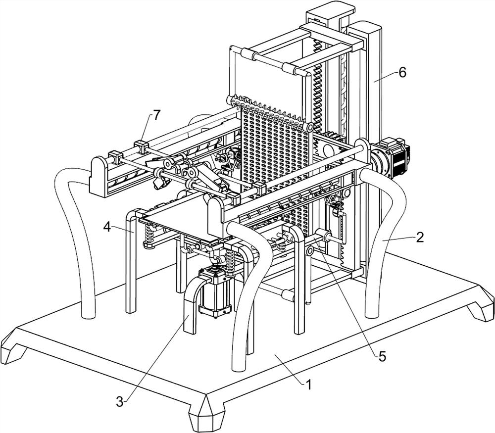
[0029] A kind of plate grinding device for PCB circuit board processing, such as figure 1 , figure 2 and image 3 As shown, it includes a base plate 1, a grinding mechanism 2 and an adsorption mechanism 3. The upper part of the base plate 1 is provided with the grinding mechanism 2, and the upper left side of the base plate 1 is provided with the adsorption mechanism 3 in the middle.
[0030] The grinding mechanism 2 includes a motor 21, a transmission assembly 22, a screw mandrel 23, a first sliding seat 24, a first sliding block 25, a connecting rod 26, a grinding plate 27 and a supporting foot 28, and the front and rear sides of the upper part of the bottom plate 1 are symmetrically connected. There are supporting feet 28, and the first sliding seat 24 is connected between the upper sides of the supporting feet 28 on the front and rear sides, and the first sliding seat 24 is connected with a screw rod 23 in a rotating manner between the left and right sides, and the right...
Embodiment 2
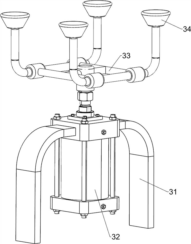
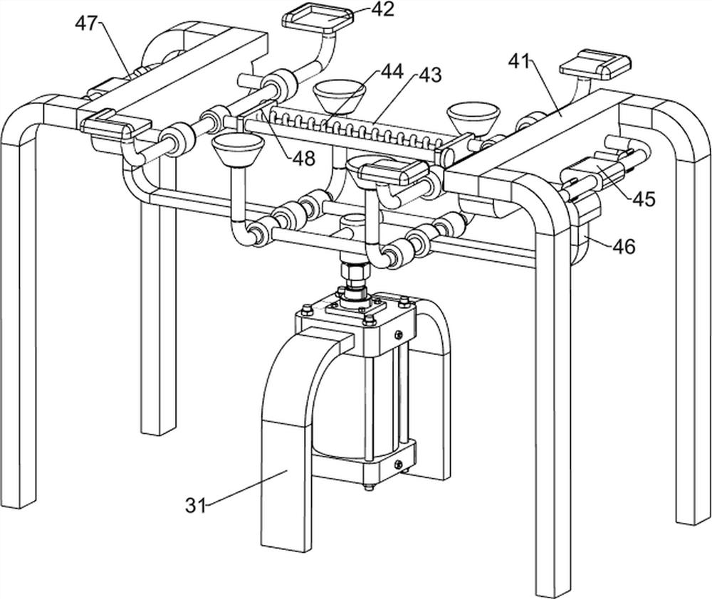
[0034] On the basis of Example 1, such as Figure 4 , Figure 5 , Figure 6 and Figure 7 As shown, also includes a limiting device 4, the limiting device 4 includes a fixed bracket 41, a chuck 42, a limiting rod 43, a first spring 44, a wedge block 45, a wedge frame 46, a sliding frame 47 and a sliding plate 48, Base plate 1 upper left side is symmetrically connected with fixed support 41 front and back, fixed support 41 upper inner side is all slidably connected with sliding frame 47, and sliding frame 47 inner side upper part is all left and right symmetrically connected with chuck 42, and sliding frame 47 inboard middle part is all connected with limited position. Rod 43, the outer side of stop bar 43 is all connected with slide plate 48, and slide plate 48 is all connected with the other side stop bar 43 slidingly, is connected with first spring 44 between slide plate 48, and the middle of first connecting frame 33 bottoms The front and rear sides are all connected wit...
PUM
 Abstract
Description
Claims
Application Information