
Preparation method of component- gradient -controllable multi-element ultrahigh-temperature ceramic modified C/C composite material

A technology of ultra-high temperature ceramics and composite materials, which is applied in the field of preparation of multi-element ultra-high temperature ceramic modified C/C composite materials with controllable composition gradient, which can solve the problems of reduced mechanical properties, improve heat insulation performance, reduce inert weight, The effect of ensuring mechanical strength

Active Publication Date: 2021-03-09
CENT SOUTH UNIV
View PDF15 Cites 12 Cited by
  • Summary
  • Abstract
  • Description
  • Claims
  • Application Information

AI Technical Summary

Problems solved by technology

[0007] Aiming at the defects existing in the actual application process of the existing homogeneous ceramic modified C / C composite material, the purpose of the present invention is to provide a method for preparing a composition gradient controllable multivariate ultra-high temperature ceramic modified C / C composite material. The multi-stage design of the high-temperature ceramic modified C / C composite material enables the two types of ceramic phases to form a continuous composition transition area inside the C / C matrix, avoiding the disadvantages of mechanical property degradation caused by composition mutations

Method used


Image

  • Preparation method of component- gradient -controllable multi-element ultrahigh-temperature ceramic modified C/C composite material
  • Preparation method of component- gradient -controllable multi-element ultrahigh-temperature ceramic modified C/C composite material
  • Preparation method of component- gradient -controllable multi-element ultrahigh-temperature ceramic modified C/C composite material

Examples


Embodiment 1

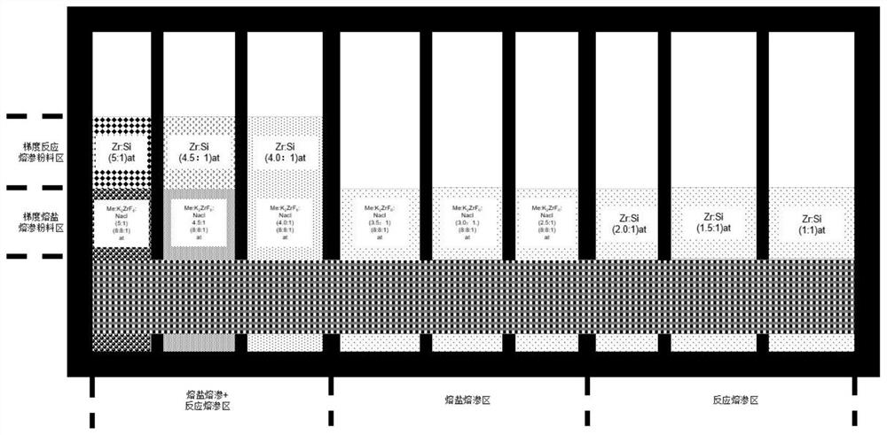
[0046] Such as figure 1 As shown, it is a schematic diagram of the placement of the graphite tank body and the powder used in this embodiment. The graphite tank body is a hollow cube, and 8 pairs of slots are sequentially opened along the length direction of the cube, and graphite plates are inserted in the slots. The graphite tank body is divided into 9 sections, from left to right, the 1st-3rd section is the front end area, the 4th-6th section is the middle end area, and the 7th-9th section is the rear end area.

[0047] (1) Add 1.2g / cm 3 The C / C composite material is polished and cleaned with absolute ethanol, and placed in an oven at 100°C for 12 hours for later use; the particle size of Zr and Si metal powders are both <200 mesh, and mixed with alcohol according to the set atomic ratio. Dry and sieve after mixing in a drum type ball mill for 12 hours for subsequent use;

[0048] (2) First, lay Zr-Si mixed common reaction infiltration powder and K 2 ZrF 6 Zr-Si mixed m...

Embodiment 2

[0053] Adopt the graphite tank body of embodiment 1 and the placement mode of powder:

[0054] (1) Add 1.2g / cm 3 After the C / C composite material is polished and polished as a whole, it is washed with absolute ethanol, and placed in an oven to dry for 12 hours at 100°C for use; the particle size of Hf and Si metal powders are both <200 mesh, and they are mixed with alcohol according to the set atomic ratio. Dry and sieve after mixing in a drum type ball mill for 12 hours for subsequent use;

[0055] (2) Firstly lay Hf-Si mixed ordinary reaction infiltration powder and K 2 ZrF 6 Hf-Si mixed molten salt infiltration powder doped with alkali metal salt, and K 2 ZrF 6 Hf-Si mixed molten salt infiltration powder doped with alkali metal salt, Hf-Si mixed ordinary reaction infiltration powder is laid on the bottom plate of the graphite tank in the 7th-9th section, and then the C / C composite material is placed on Inside the graphite tank, insert the required graphite plates on bo...

Embodiment 3

[0060] like Figure 4 As shown, it is a schematic diagram of the placement of the graphite tank body and the powder used in this embodiment. The graphite tank body is a hollow cube, and 8 pairs of slots are sequentially opened along the length direction of the cube, and graphite plates are inserted in the slots. The graphite tank body is divided into 9 sections, from left to right, the 1st-3rd section is the front end area, the 4th-6th section is the middle end area, and the 7th-9th section is the rear end area; in this embodiment, each section The amount of powder placed is the same as in Example 1. The scheme of Example 1 is a one-step molding process, while the second scheme of this example is a two-step molding process. The difference in the way of powder placement is only the K in Example 1. 2 ZrF 6 Lay together with alkali metal salt doped Zr-Si mixed molten salt infiltration powder and Me-Si mixed common reaction infiltration powder, and K in this embodiment 2 ZrF 6 ...


PUM

PropertyMeasurementUnit
densityaaaaaaaaaa
porosityaaaaaaaaaa

Abstract

The invention discloses a preparation method of a component-gradient-controllable multi-element ultrahigh-temperature ceramic modified C / C composite material. Through multi-section design of various ultrahigh-temperature ceramics (ZrC, HfC, HfB2 and the like) and high-temperature ceramic (SiC) composite modified C / C composite materials, a ceramic phase forms a continuous component gradient distribution form in a C / C matrix, ablation resistance and oxidation resistance requirements of different temperature range fields are met regionally, and meanwhile the defect that the mechanical property isreduced due to component mutation is overcome. According to the invention, a preparation process of combining molten salt infiltration and common reaction infiltration and gradient infiltration powder configuration are adopted in sections, so that near-ablation-end strong ceramic phase interface design is realized, and ceramic phase distribution realizing that the content of an ultrahigh-temperature ceramic phase is sequentially decreased from the near ablation end to a far ablation end and the high-temperature ceramic phase is sequentially increased is regulated and controlled; finally, thegradient ceramic-based composite material with different ceramic phase components and contents in gradient change and meeting the performance requirements of the material is formed.

Description

technical field [0001] The invention belongs to the technical field of C / C composite material preparation, and in particular relates to a preparation method of C / C composite material modified by multi-component ultra-high temperature ceramics with controllable composition gradient. Background technique [0002] With the rapid development of aerospace vehicles, the environment faced by key thermal protection structural parts of hypersonic vehicles is becoming more and more severe. During the flight of the aircraft, the surface of the wing and leading edge is subjected to the test of high temperature oxidation, mechanical and shock load impact, especially the inner wall near the heat insulation layer needs to withstand a temperature drop of 1000 °C. This puts great demands on the constituent materials of key thermal structural parts, that is, it needs to meet the ablation resistance of the material surface, the oxidation resistance of the inner surface at a lower temperature r...

Claims


Application Information

Patent Timeline
Patent Type & Authority Applications(China)
IPC IPC(8): C04B41/87
CPCC04B41/009C04B41/5059C04B41/87C04B41/5057C04B41/4556C04B41/4523C04B35/83C04B38/00
Inventor 孙威田甜熊翔张红波曾毅王雅雷陈招科尹健
Owner CENT SOUTH UNIV
Learn More