


Quick Research
Generate reliable direction feasibility study reports for your R&D in just a few steps.

Technical Q&A
Discover and master advanced knowledge NOW. Basics, ideas, possibilities, all at once.

Find Solutions
As an expert in R&D theories, this can generate solutions to your technical problems instantly.

Evaluate Feasibility
Analyze your overall solution with one click, know your potential R&D risks in advance.

Monitor Landscape
Get weekly tech updates, stay abreast of the latest tech innovations and key insights.
Biodiesel combustion stove
A biodiesel and stove technology, applied in the field of stoves, can solve the problems of restricting the applicability of the stove core, the inability to achieve dual-use of oil and gas, etc., and achieve the effect of improving convenience, improving utilization rate, and simplifying the output structure
- Summary
- Abstract
- Description
- Claims
- Application Information
AI Technical Summary
Problems solved by technology
Method used
Image

Examples
Embodiment 1
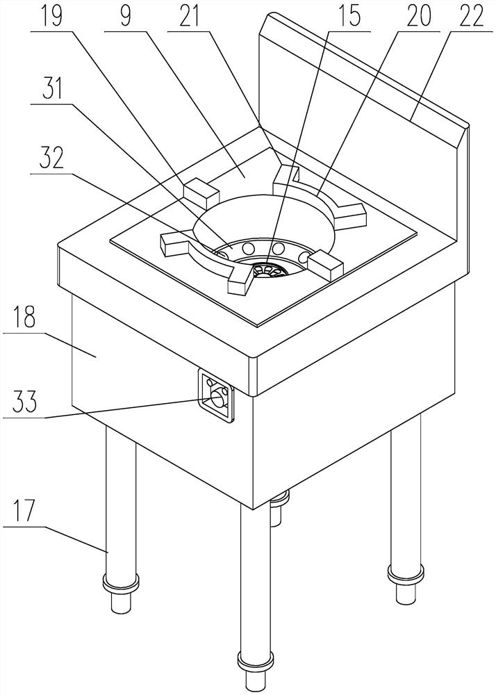
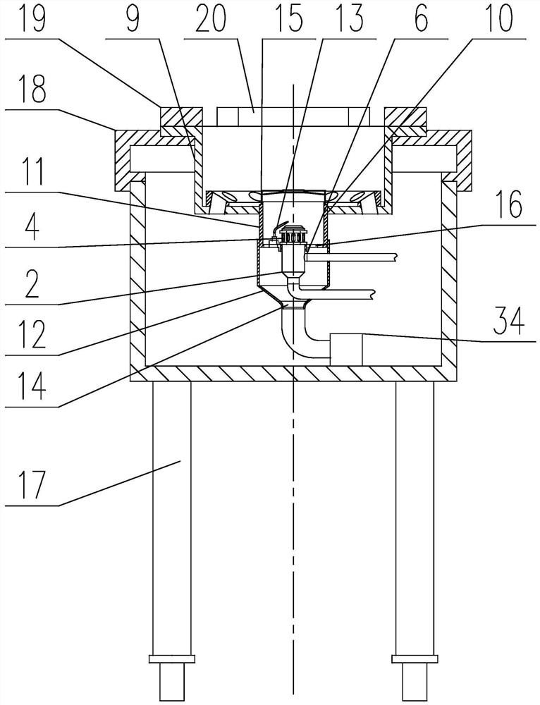
[0038] Such as Figure 2 to Figure 7 As shown, a biodiesel burning stove of the present invention includes a stove shell 18 supported on the ground by feet 17 and a furnace core structure sunkenly installed on the upper surface of the stove shell 18. The furnace core structure includes a uniform The outer core tube 9 vertically placed in the inner cavity of the stove shell 18, the inner core tube 11 installed below the central hole 10 at the bottom of the outer core tube 9, and the inner core tube 11 installed at the bottom of the inner core tube 11 and inserted into the inner hole of the inner core tube 11 at the top Fuel nozzle 2, where,
[0039] The top of the outer core tube 9 is connected to the upper side wall of the stove shell 18, and the bottom of the inner hole of the inner core tube 11 is installed with an ignition needle 13;
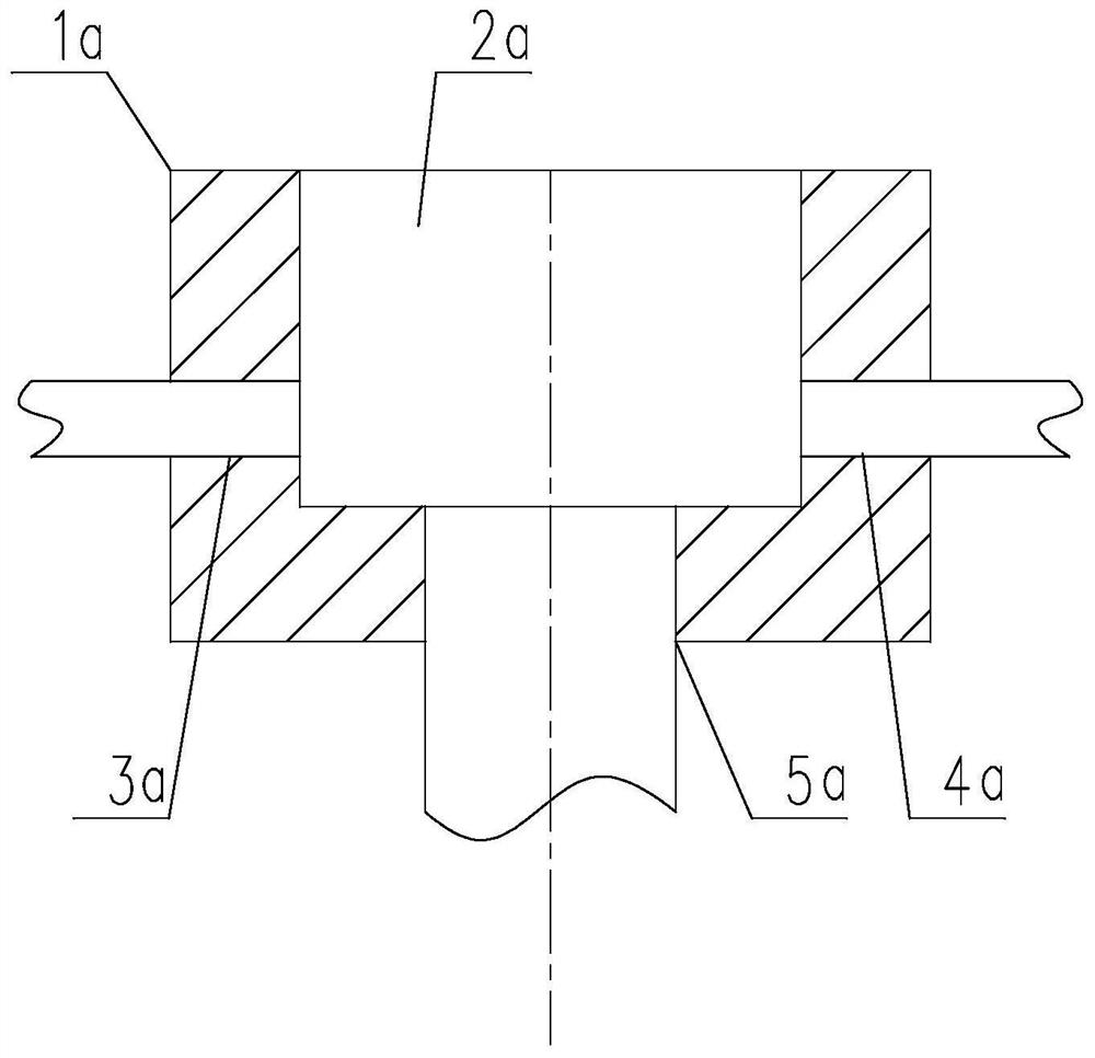
[0040]The inside of the nozzle 2 is provided with an oil flow channel 1 and a gas flow channel 3 which are independent of each other. The i...
Embodiment 2
[0046] This embodiment is based on the embodiment 1, and makes a specific implementation description for the layout of the gas flow channel 3 and the oil flow channel 1 .
[0047] Such as Figure 7 As shown, in the present invention, the gas flow channel 3 is an annular structure surrounding the oil flow channel 1 , and the gas outlets 4 are symmetrically distributed along the axis of the nozzle 2 .
[0048] Further, the bottom end of the oil flow channel 1 first extends along the axis of the nozzle 2, then extends along the radial direction of the nozzle 2 and then passes through one side of the gas flow channel 3 and then passes out from the side of the nozzle 2, A partition pipe 6 is installed at the intersecting part of the gas flow passage 3 and the oil flow passage 1, and the outer wall of one end of the partition pipe 6 is in sealing connection with the wall surface of the oil flow passage 1, and the other end of the separation pipe 6 is connected along the oil flow pas...
Embodiment 3
[0056] This embodiment is based on the above-mentioned embodiments to further illustrate the implementation of the present invention.
[0057] In the present invention, an air-inducing tube 12 is threaded on the bottom of the inner core tube 11, and the bottom of the air-inducing tube 12 is provided with an air inlet 14, and its bottom is in the shape of an inverted cone. The wall is provided with a first through hole for the intake pipe to pass through and a second through hole for the oil intake pipe to pass through, and the bottom of the inner core tube 11 is provided with an air intake through hole 16 .
[0058] The fan sends air to the air-inducing tube 12 through the pipe, and the air enters the inner core tube 11 through the air-inlet through hole 16, thereby supporting the combustion of the gas or biodiesel from the nozzle and improving the thoroughness of fuel combustion; at the same time, the air-inducing tube 12 The setting can direct the air from the fan to the sur...
PUM
 Abstract
Description
Claims
Application Information
 - R&D Engineer
- R&D Manager
- IP Professional
- Industry Leading Data Capabilities
- Powerful AI technology
- Patent DNA Extraction
Browse by: Latest US Patents, China's latest patents, Technical Efficacy Thesaurus, Application Domain, Technology Topic, Popular Technical Reports.
© 2024 PatSnap. All rights reserved.Legal|Privacy policy|Modern Slavery Act Transparency Statement|Sitemap|About US| Contact US: help@patsnap.com