Gasification combustor for biomass granules

A biomass particle and burner technology, which is used in combustion equipment, solid fuel combustion, lighting and heating equipment, etc., can solve the problems of insufficient gasification of biomass particles, low thermal efficiency of semi-gasification, and unpleasant smell. , to achieve the effect of compact structure, small footprint, simple and convenient installation

Active Publication Date: 2011-11-23
穆壮荣
View PDF7 Cites 17 Cited by
  • Summary
  • Abstract
  • Description
  • Claims
  • Application Information

AI Technical Summary

Problems solved by technology

The direct-fired gasifier generates gasification combustion through the secondary air intake, and the biomass particles are not fully gasified, which wastes energy
Semi-gasification type has low thermal efficiency and low calorific value
Gas-guided gasifiers are divided into up-suction type and down-suction type, etc., which use the principle of thermochemical reaction to generate combustible gas combustion. Ignition after the wind, the disadvantage of the gas-guided gasifier is that it produces a large amount of tar, waste water, and bad smell, causing secondary pollution

Method used


Image

  • Gasification combustor for biomass granules
  • Gasification combustor for biomass granules
  • Gasification combustor for biomass granules

Examples


Embodiment 1

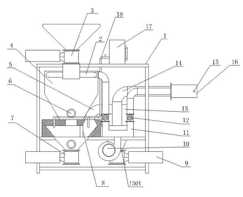
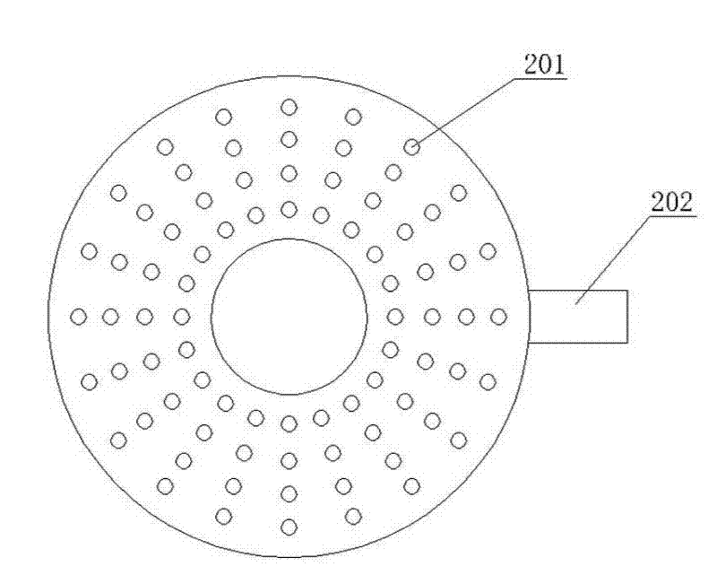
[0023] Such as Figure 1 to Figure 5 As shown, the biomass particle gasification burner has a housing 1, a packing device 3 is arranged on the housing 1, an inner tank 4 and a blower 10 are arranged in the housing 1, and an annular diffuser is arranged on the upper part of the inner tank 4. The diffuser 2 is provided with a plurality of diffuser holes 201 on the top surface of the diffuser 2 (facing the upper wall of the liner 4 ), and an air inlet 202 is provided on the side of the diffuser 2 . The lower part of the inner container 4 is provided with an ignition port 6, a fire grate 8 and an ash outlet. The area between the carbonization area and the fire grate 8 is the reduction area, and the area outside the fire grate 8 is the gasification area. Outer shell 1 is provided with water tank 17, draws water supply pipe 18 on water tank 17, is provided with valve on water supply pipe 18, and water supply pipe 18 water outlets are positioned at the reducing area of ​​liner 4 bo...

Embodiment 2

[0026] Such as Figure 6 As shown, for the small burner, the water tank 17 and the water supply pipe 18 in the embodiment 1 are canceled, and the moisture contained in the biomass particles is mixed with the air from the blower 10 to form saturated air as the gasification agent, and the others are the same as in the embodiment 1.

Embodiment 3

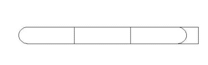
[0028] Such as Figure 7 As shown, the filter 13 is a box, and a plurality of partitions 19 are vertically placed in the filter 13. The partitions 19 are arranged in a staggered up and down manner to form a serpentine passage, and ash discharge is provided at the bottom of the serpentine passage. The mouth 1301, the outlet of the connecting pipe 5 and the inlet of the gas pipe 14 are respectively located at the beginning and end of the serpentine passage. The mixed combustible gas entering the filter 13 is discharged through the serpentine channel, and the dust is discharged through the ash discharge port 1301 . Others are with embodiment 1.


PUM


Abstract

The invention relates to a gasification combustor for biomass granules. The gasification combustor comprises a shell, wherein a filler device is arranged on the shell; an inner container and a blast blower are arranged in the shell; and an ignition tuyere and a fire grate is formed on the lower part of the inner container. The gasification combustor is characterized in that: an annular air diffuser is arranged on the upper part in the inner container; a carbonization area corresponds to the ignition tuyere in the inner container, a reduction area is positioned between the carbonization area and the fire grate, and a gasification area is positioned outside the fire grate; the gasification area is connected with a filter by a connection pipe; a gas pipe is arranged at an outlet of the filter; an ash discharge opening is formed at the bottom of the filter; a burner and an ignition device are arranged at the lead-out end led out of the filter and the shell on the gas pipe; and the blast blower is connected with the air diffuser and the burner respectively by a pipeline and a valve arranged on the pipeline. The gasification combustor can gasify the biomass granules fully, is good in combustion effect, high in heat efficiency and heat value, energy-saving, low-carbon, environment-friendly and low in discharge, can replace fuel oil, gas and fire coal, and does not have oil tar, wastewater and smoke dust; and the gasification combustor has a compact structure, and is easy and convenient to mount, small in space occupation and wide in application range.

Description

technical field [0001] The invention relates to a biomass particle gasification burner which uses biomass particle fuel to generate combustible gas. Background technique [0002] Existing burners that use biomass particles as fuel can be roughly divided into three categories: direct combustion, semi-gasification and gas-guided (gas-making) types. The direct-fired gasifier generates gasification combustion through the secondary air intake, and the biomass particles are not fully gasified, which wastes energy. The semi-gasification type has low thermal efficiency and low calorific value. Gas-guided gasifiers are divided into up-suction type and down-suction type, etc., which use the principle of thermochemical reaction to generate combustible gas combustion. Ignition after the wind, the disadvantage of the gas-guided gasifier is that it produces a large amount of tar, waste water, and bad smell, causing secondary pollution. Contents of the invention [0003] The present i...

Claims


Application Information

Patent Timeline
Patent Type & Authority Applications(China)
IPC IPC(8): F23B90/06
Inventor 穆壮荣
Owner 穆壮荣
Why Eureka
Try Eureka