Gas generator for air bag and air bag apparatus

a gas generator and air bag technology, applied in the directions of separation processes, pedestrian/occupant safety arrangements, vehicular safety arrangements, etc., can solve the problems of large container size, high cost, complicated internal structure,

Inactive Publication Date: 2002-05-16
DAICEL CHEM IND LTD
View PDF0 Cites 16 Cited by
  • Summary
  • Abstract
  • Description
  • Claims
  • Application Information

AI Technical Summary

Problems solved by technology

However, these gas generators have drawbacks in that an internal structure thereof is complicated, a size of a container large, and a cost therefor is expensive.
Further, since the ratio between a surface area of gas generating agent, which burns at each of stages, and an area of a nozzle for controlling the combustion is not preferable over the entire stages, the internal pressure in the housing may be excessively low in the combustion of the first stage and excessively high in the combustion of the second stage, and therefore, it is not possible to control inflation of the air bag appropriately.
However, in any of the gas generators, since the igniters arranged in the respective combustion chambers are independently arranged, it is difficult to assemble (manufacture), the structure itself of the gas generator becomes complicated and a volume thereof becomes large.
However, in the case of burning the second gas generating agent after about 30 milliseconds, the combustion gas of the first gas generating agent has been discharged during that period, whereby the combustion internal pressure at the time of burning the second gas generating agent becomes slightly lower as compared with the case when the two gas generating agents are burnt simultaneously, and it is not optimal combustion environment for burning the second gas generating agent.
Accordingly, if one kind of gas discharge ports is opened at one time from the initial stage, it is difficult to meet all of the combustion modes.
And as a result, the combustion internal pressure when the first gas generating agent is burnt is low, which brings a great difference with the internal pressure when the second gas generating agent is burnt.
However, the number of the holes and the arrangement structure are determined in connection with an easiness for manufacturing the gas generating agent, a manufacture cost and a performance, and are not particularly limited.

Method used


Image

  • Gas generator for air bag and air bag apparatus
  • Gas generator for air bag and air bag apparatus
  • Gas generator for air bag and air bag apparatus

Examples


embodiment 1

[0055] Embodiment 1

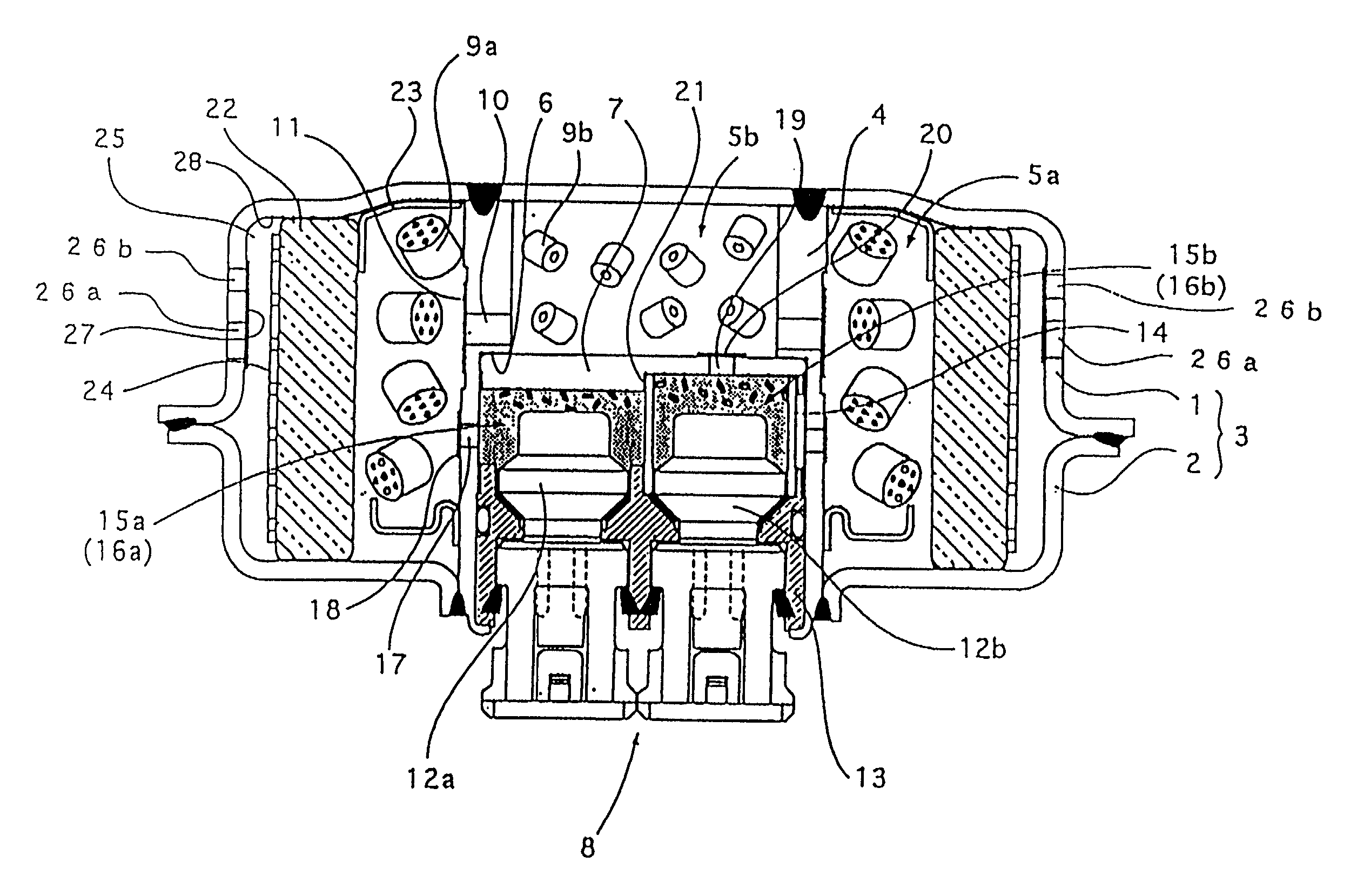
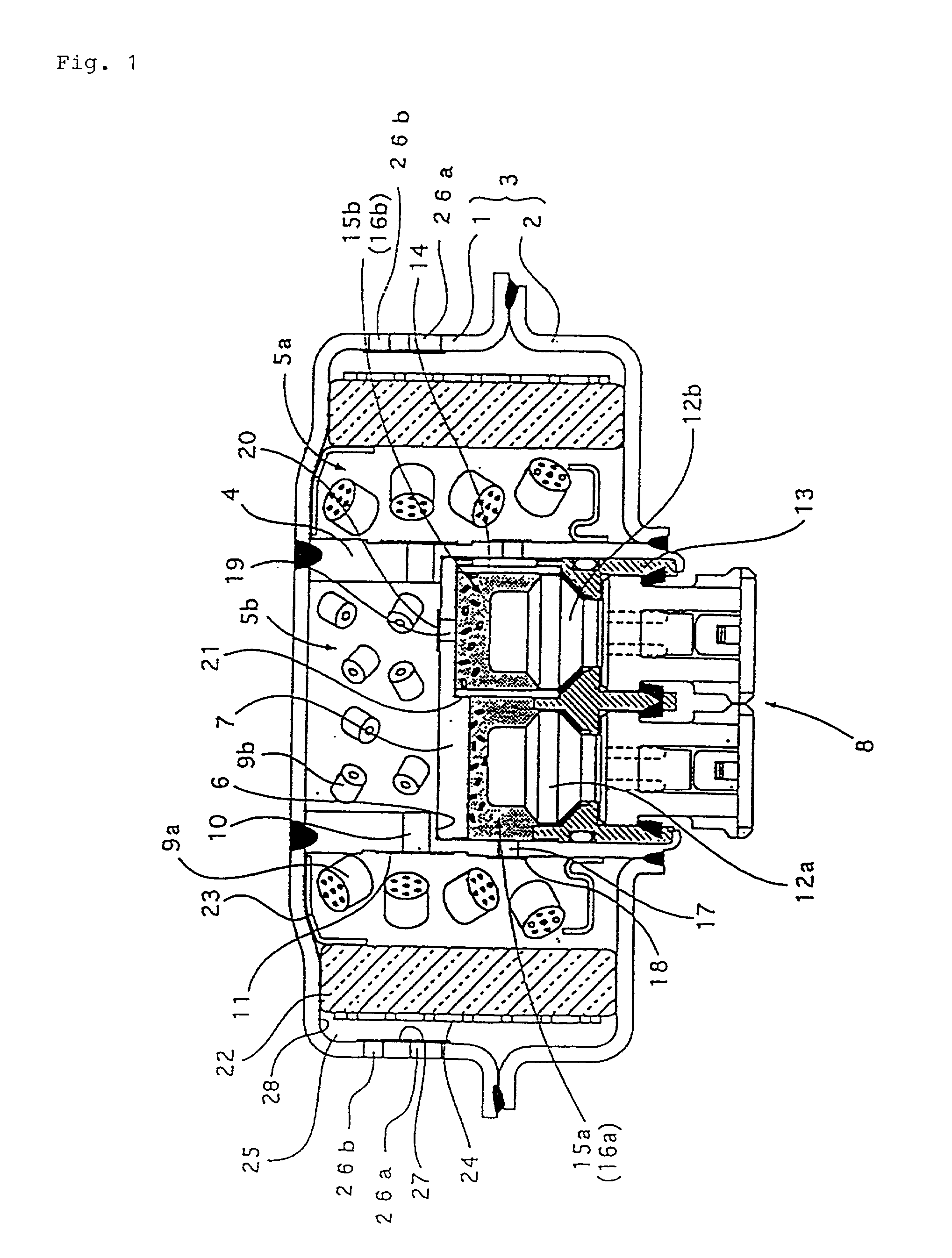
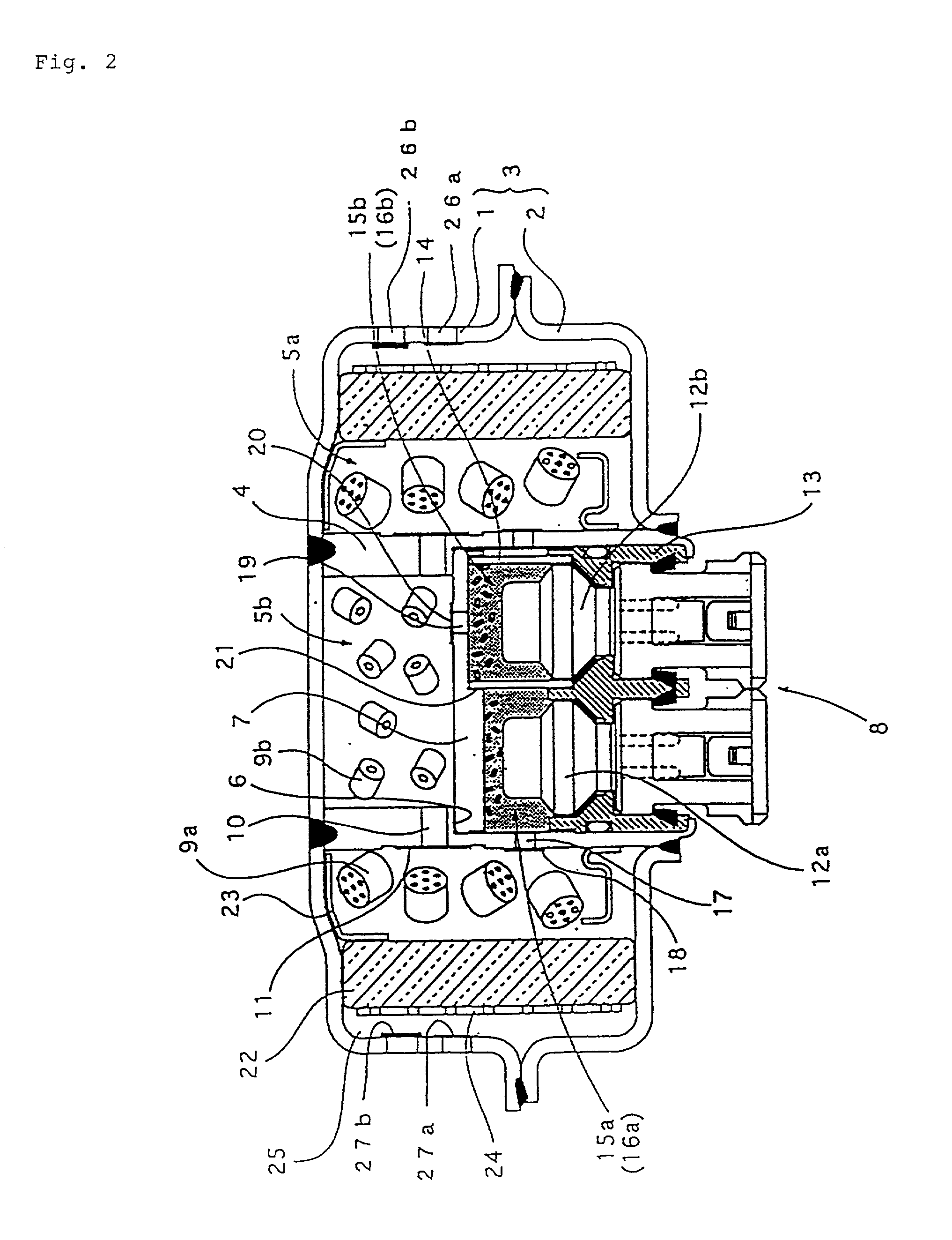
[0056] FIG. 1 is a vertical cross sectional view of a first embodiment of a gas generator for an air bag according to the present invention, which shows a structure particularly suitable for being arranged in a driver side.

[0057] The gas generator comprises a housing 3 which is formed by joining a diffuser shell 1 with gas discharge ports and a closure shell 2 forming a inner accommodating space with the diffuser shell, and an inner cylindrical member 4 formed in a substantially cylindrical shape arranged in the housing 3, thereby forming a first combustion chamber 5a by an outer side of the inner cylindrical member 4. Further, a stepped notch portion 6 is provided inside the inner cylindrical member, a partition wall 7 formed in a substantially flat circular shape is arranged in the stepped notch portion, the partition wall further partitions an inner portion of the inner cylinder into two chambers to form a second combustion chamber 5b in the diffuser shell side...

embodiment 2

[0072] Embodiment 2

[0073] FIG. 3 is a vertical cross sectional view which shows another embodiment of a gas generator for an air bag according to the present invention. This gas generator is structured such as to be particularly suitable for being arranged in a passenger side of the vehicle.

[0074] The gas generator shown in this drawing has, in the housing 103 formed into a cylindrical shape having an axial core length longer than an outermost diameter and having a plurality of gas discharge ports on a peripheral wall thereof, ignition means actuated upon an impact, gas generating agents (9a, 9b) ignited and burnt by the ignition means and generate a combustion gas for inflating the air bag, and a coolant / filter 122 for cooling and / or purifying the combustion gas generated by the combustion of the gas generating agents. Two combustion chambers (105a, 105b) provided in the housing 103 are concentrically provided so as to be adjacent to each other with respect to an axial direction of...

embodiment 3

[0086] Embodiment 3

[0087] FIG. 5 is a vertical cross sectional view showing a gas generator for an air bag of the present invention in another embodiment. The gas generator shown in this embodiment also has a structure suitable for being disposed in the driver side like the gas generators shown in FIGS. 1 and 2.

[0088] The gas generator shown in FIG. 5 has the same structure as that shown in FIG. 1 except a structure of a partition wall which defines a cylindrical member into a second combustion chamber and an ignition means accommodating chamber. Therefore, the same members as those shown in FIG. 1 are designated with the same numerals, and explanation thereof is omitted.

[0089] Particularly in the gas generator shown in this figure, the partition wall 307, having a substantially flat curricular shape, which partitions the interior of the inner cylinder into the second combustion chamber and the ignition means accommodating chamber, is, as shown in an exploded perspective view in FIG...


PUM

PropertyMeasurementUnit
diameteraaaaaaaaaa
diameteraaaaaaaaaa
diameteraaaaaaaaaa

Abstract

A gas generator small in size and which can be produced easily with a simple structure is provided. The output of a gas generator is equalized so that an occupant can be safely restrained, and the combustion performance can be stably adjusted. The gas generator comprises a housing forming an outer shell container and accommodating two or more ignition units to ignite upon an impact and two or more gas generating agents which are independently ignited and burnt by the ignition units to generate a combustion gas for inflating an air bag, and a plurality of gas discharge ports which are formed in the housing, wherein the gas discharge ports are closed by sealing units for maintaining an internal pressure of the housing to the given pressure, a breaking pressure for breaking the sealing units is adjusted in multiple stages by controlling gas discharge ports and/or sealing units, and a difference of the maximum internal pressures in the housing at activation of the respective igniters is suppressed.

Description

[0001] This application is a divisional of co-pending application Ser. No. 09 / 554,123, filed on Jul. 10, 2000 and for which priority is claimed under 35 U.S.C. .sctn.120. application Ser. No. 09 / 554,123 is the national phase of PCT International Application No. PCT / JP99 / 06701 filed on Nov. 30, 1999 under 35 U.S.C. .sctn.371. The entire contents of each of the above-identified applications are hereby incorporated by reference. This application also claims priority of Application Nos. 10-339934; 11-78306; and 11-338174 filed in Japan on Nov. 30, 1998; Mar. 23, 1999; and Nov. 29, 1999 under 35 U.S.C. .sctn.119.[0002] 1. Field of the Invention[0003] The present invention relates to a gas generator for an air bag and an air bag apparatus including two or more ignition means and two or more gas generating means for controlling discharge of gas or behavior of flow of the gas.[0004] 2. Description of Related Art[0005] An air bag system which is mounted on various kinds of vehicles and the l...

Claims


Application Information

Patent Timeline
Patent Type & Authority Applications(United States)
IPC IPC(8): B60R21/264B01D46/24B60R21/01B60R21/217B60R21/26B60R21/263
CPCB01D46/24B01D46/2403B01D2279/10B60R2021/2648B60R2021/01006B60R2021/26064B60R2021/2633B60R21/2644B60R21/217B60R21/26B60R21/264
Inventor NAKASHIMA, YOSHIHIROOHJI, NOBUYUKI
Owner DAICEL CHEM IND LTD
Why Eureka
Try Eureka