
Preparation method of silicon-on-insulator micro-display and micro-display

A silicon-on-insulator and microdisplay technology, which is applied in semiconductor/solid-state device manufacturing, semiconductor devices, electric solid-state devices, etc., can solve problems such as transistor performance degradation, achieve a wide range of material selection, and solve the effect of limited material supply

Pending Publication Date: 2021-03-09
ANHUI SEMICON INTEGRATED DISPLAY TECH CO LTD
View PDF0 Cites 0 Cited by
  • Summary
  • Abstract
  • Description
  • Claims
  • Application Information

AI Technical Summary

Problems solved by technology

However, the current display screens have the problem of degradation of transistor performance due to the strong backlight irradiating the transistors driving the pixel units.

Method used


Image

  • Preparation method of silicon-on-insulator micro-display and micro-display
  • Preparation method of silicon-on-insulator micro-display and micro-display
  • Preparation method of silicon-on-insulator micro-display and micro-display

Examples


Embodiment Construction

[0033] Specific embodiments of the present invention will be described in detail below in conjunction with the accompanying drawings. It should be understood that the specific embodiments described here are only used to illustrate and explain the present invention, and are not intended to limit the present invention.

[0034] In the present invention, unless stated otherwise, the orientation words included in the term such as "up, down, left, and right" only represent the orientation of the term in the normal use state, or the common name understood by those skilled in the art, rather than should be considered a limitation of the term.

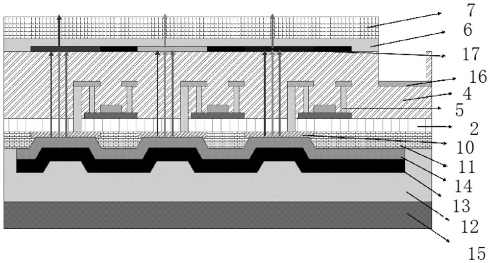
[0035] Figure 11 It is a flowchart of a method for preparing a silicon-on-insulator microdisplay provided by the present invention, such as Figure 11 As shown, the preparation method of the silicon-on-insulator microdisplay comprises:

[0036] S101, providing a silicon-on-insulator substrate, wherein the upper silicon substrate includes a...


PUM


Abstract

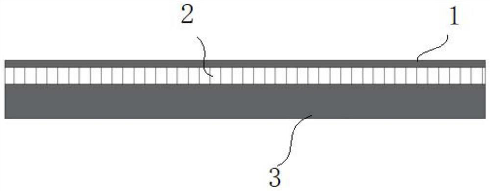
The invention discloses a preparation method of a silicon-on-insulator micro-display and the micro-display. The preparation method comprises the following steps: providing a silicon-on-insulator substrate; manufacturing a driving circuit on the outer side of the upper silicon layer, and coating an upper insulator layer; manufacturing a black matrix, an RGB optical filter and a gasket opening on the outer side of the upper insulator layer, and forming a protective layer on the black matrix and the RGB optical filter; sequentially fixing a glass cover plate and a first slide glass on the outer side of the protective layer; completely grinding off the lower silicon layer to expose the silicon dioxide layer; manufacturing via holes in the silicon dioxide layer and the insulator; manufacturinga transparent electrode and a pixel definition layer on the outer side of the exposed silicon dioxide layer; sequentially manufacturing a packaging layer, a non-transparent electrode and a light-emitting layer on the outer sides of the transparent electrode and the pixel definition layer; fixing a second slide glass on the outer side of the light-emitting layer; and stripping the first slide glassand bonding to obtain the micro-display. The reliability of the micro-display driving backboard and the display screen is improved.

Description

technical field [0001] The invention relates to a silicon-on-insulator microdisplay structure, in particular to a method for preparing a silicon-on-insulator microdisplay and the microdisplay. Background technique [0002] A method for preparing a high-contrast transmissive silicon-based liquid crystal micro-display is disclosed in the prior art, which is to make chromium on the reverse side of the transparent silicon-based driving backplane of the micro-display at the driving unit and wiring of the pixel / Chrome oxide shading lines to reduce crosstalk between pixels and improve the contrast of the display. However, in the present display screen, the performance of the transistors driving the pixel units is degraded due to the strong backlight irradiating the transistors driving the pixel units. Contents of the invention [0003] The purpose of the present invention is to provide a method for preparing a silicon-on-insulator microdisplay, which can avoid the problem of d...

Claims


Application Information

Patent Timeline
IPC IPC(8): H01L27/32H01L51/56
CPCH10K59/40H10K59/122H10K71/00
Inventor 吕迅
Owner ANHUI SEMICON INTEGRATED DISPLAY TECH CO LTD
Learn More