Automatic welding equipment for vehicle-mounted fuel tank production

An automatic welding and fuel tank technology, applied in welding equipment, welding equipment, auxiliary welding equipment, etc., can solve problems such as low work efficiency, difficult welding methods, low welding strength and welding quality, and achieve convenient protection and improved practicability and reliability, and the effect of improving usability

Active Publication Date: 2021-03-12
山东艾泰克环保科技股份有限公司
View PDF10 Cites 1 Cited by
  • Summary
  • Abstract
  • Description
  • Claims
  • Application Information

AI Technical Summary

Problems solved by technology

[0002] As we all know, the vehicle-mounted fuel tank is an auxiliary device for storing fuel. It is mainly used on heavy trucks, light trucks and other fuel transport vehicles. When the vehicle-mounted fuel tank is processed and produced, it usually needs to be welded around its docking position. The existing welding methods are mainly Workers use a welding torch to perform manual welding. When this method is used, the worker needs to hold the welding torch to perform circular welding around the outer wall of the fuel tank. The welding method is more difficult, the welding takes a long time, consumes a lot of physical strength, and the work efficiency is low. At the same time, the welding torch moves Poor stability, poor distribution uniformity of solder joints at the docking position, low welding strength and welding quality

Method used


Image

  • Automatic welding equipment for vehicle-mounted fuel tank production
  • Automatic welding equipment for vehicle-mounted fuel tank production
  • Automatic welding equipment for vehicle-mounted fuel tank production

Examples


Embodiment Construction

[0021] The specific implementation manners of the present invention will be further described in detail below in conjunction with the accompanying drawings and embodiments. The following examples are used to illustrate the present invention, but are not intended to limit the scope of the present invention.

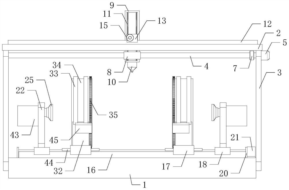
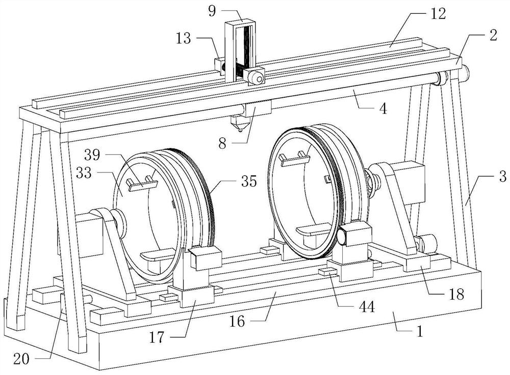
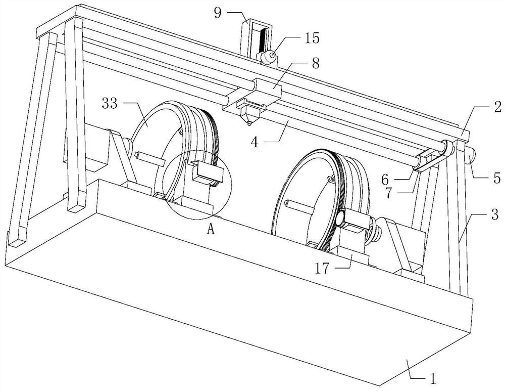
[0022] Such as Figure 1 to Figure 7 As shown, the automatic welding equipment for the production of a vehicle-mounted fuel tank of the present invention fixes the external fuel tank originals to be spliced ​​and welded on two sets of fixing devices when it is working, the docking positions of the two sets of originals are opposite, and the power unit Control the two groups of adsorption devices to approach each other, the inner sides of the two groups of adsorption devices are respectively in contact with the outer walls of the two groups of originals, open the two groups of adsorption devices, and the two groups of adsorption devices respectively carry out adsorption and...


PUM


Abstract

The invention relates to the technical field of mechanical equipment, in particular to automatic welding equipment for vehicle-mounted fuel tank production. The automatic welding equipment can conveniently improve the distribution uniformity of welding spots on a fuel tank, effectively improve the strength and the welding quality of a welding machine by performing automatic welding treatment on the fuel tank, and meanwhile, simplify the welding mode, effectively save physical strength during manual welding, improve working efficiency and improve practicability and reliability. The automatic welding equipment comprises a workbench, a top beam, four first supporting plates, two first lead screws and a first motor, a power device is transversely arranged at the top of the workbench, adsorption devices are arranged on the left side and the right side of the top of the power device, the two adsorption devices are opposite in direction, two fixing devices are arranged between the two adsorption devices, and the two fixing devices are opposite in direction, the bottoms of the two fixing devices are installed on the left side and the right side of the power device correspondingly.

Description

technical field [0001] The invention relates to the technical field of mechanical equipment, in particular to an automatic welding equipment for the production of vehicle-mounted fuel tanks. Background technique [0002] As we all know, the vehicle-mounted fuel tank is an auxiliary device for storing fuel. It is mainly used on heavy trucks, light trucks and other fuel transport vehicles. When the vehicle-mounted fuel tank is processed and produced, it usually needs to be welded around its docking position. The existing welding methods are mainly Workers use a welding torch to perform manual welding. When this method is used, the worker needs to hold the welding torch to perform circular welding around the outer wall of the fuel tank. The welding method is more difficult, the welding takes a long time, consumes a lot of physical strength, and the work efficiency is low. At the same time, the welding torch moves The stability is poor, the distribution uniformity of the solder ...

Claims


Application Information

Patent Timeline
Patent Type & Authority Applications(China)
IPC IPC(8): B23K26/21B23K26/70B23K26/08B23K37/04
CPCB23K26/21B23K26/702B23K26/0869B23K37/04B23K2101/12B23K2101/006
Inventor 宋志勤
Owner 山东艾泰克环保科技股份有限公司
Why Eureka
Try Eureka