
A transmission mirror and its application in reducing the risk of backscattered light damage to laser drivers

A technology of mirrors and transmission optical paths, applied in the field of optical components, can solve the problems of unsupported dielectric film technology

Active Publication Date: 2022-04-22
LASER FUSION RES CENT CHINA ACAD OF ENG PHYSICS
View PDF17 Cites 0 Cited by
  • Summary
  • Abstract
  • Description
  • Claims
  • Application Information

AI Technical Summary

Problems solved by technology

If the transmission mirror is coated with a 351nm high-reflection film, the 351nm laser damage threshold of the baseband components must be increased to 2J / cm 2 Left and right, the current level of dielectric film technology cannot support

Method used


Image

  • A transmission mirror and its application in reducing the risk of backscattered light damage to laser drivers
  • A transmission mirror and its application in reducing the risk of backscattered light damage to laser drivers
  • A transmission mirror and its application in reducing the risk of backscattered light damage to laser drivers

Examples


Embodiment

[0030] A transmission mirror prepared by the following method:

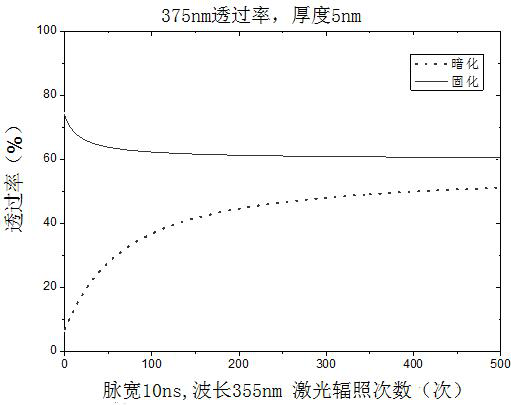
[0031]Take a K9 optical material (transmission mirror) with a size of 10mm×10mm×2mm, wash it with acetone and dry it, and then irradiate it with gamma rays at a dose rate of 80Gy / min. The irradiation atmosphere is air, and the total absorbed dose of the glass After the irradiation, the sample was placed in a constant temperature annealing furnace at 300°C for 12 hours and annealed for 12 hours. After testing the optical properties of the material, an optical material with stable color center curing was obtained, and its transmittance was stable around 77.5%.

[0032] The surface of the transmission mirror is then subjected to conventional optical processing;

[0033] Irradiate the transmission mirror after optical processing with 500 rounds of ultraviolet pulsed laser, the pulse width is 10ns, and the energy density is 2J / cm 2 ;

[0034] Coating high-threshold reflective film on the reflective surface cured by ...


PUM

PropertyMeasurementUnit
optical damage thresholdaaaaaaaaaa
reflectanceaaaaaaaaaa
transmittivityaaaaaaaaaa

Abstract

The invention discloses a transmission reflection mirror and its application in reducing the risk of backscattered light damage to a laser driver, belonging to the technical field of optical elements. The preparation steps of the transmission reflection mirror of the invention include: using high-energy rays to irradiate K9 optical Material, annealing and curing material color center, optical processing transmission mirror surface, ultraviolet laser radiation curing color center, coating high threshold reflection film on the reflection surface of transmission mirror; Reflection and re-reflection to reduce the risk of backscattered light damage to the laser driver.

Description

technical field [0001] The invention relates to the technical field of optical components, in particular to a transmission mirror and its application in reducing the risk of damage to a laser driver caused by backscattered light. Background technique [0002] It is the first link of various high-energy-density physical processes driven by laser to generate plasma and couple with it when laser is incident on the target. When the laser interacts with the plasma, the electrons in the plasma oscillate along the electric field polarization direction in the laser electromagnetic field. Ideally, these oscillating electrons can exchange energy to ions through collisions, change the state of ion shell electrons and pass subsequent recombination , Transition and other processes emit X-rays. Then, if there is a disturbance in the plasma density at the initial moment, a large number of oscillating electrons combined with the density disturbance will form an oscillating current along th...

Claims


Application Information

Patent Timeline
Patent Type & Authority Patents(China)
IPC IPC(8): G02B5/08
CPCG02B5/0808
Inventor 王方朱启华刘红婕郑天然田野胡东霞陈元向勇袁晓东
Owner LASER FUSION RES CENT CHINA ACAD OF ENG PHYSICS
Features
  • Generate Ideas
  • Intellectual Property
  • Life Sciences
  • Materials
  • Tech Scout
  • Unparalleled Data Quality
  • Higher Quality Content
  • 60% Fewer Hallucinations
Learn More