
Explosion-proof high-efficiency hydraulic piling hammer control system and piling method thereof

A hydraulic piling hammer and control system technology, applied in the direction of fluid pressure actuation system safety, fluid pressure actuation system components, sheet pile walls, etc., can solve the problems of reducing piling efficiency, piling energy loss, redundant sensitivity, etc., to achieve action The effect of high execution efficiency, shortened lifting time, and improved piling efficiency

Pending Publication Date: 2021-01-01
无锡市汉为液压气动有限公司
View PDF0 Cites 0 Cited by
  • Summary
  • Abstract
  • Description
  • Claims
  • Application Information

AI Technical Summary

Problems solved by technology

[0003] First, the control efficiency is low. Due to the complex control system of the hydraulic pile driver, a combination of various valve actions is used to meet the control requirements, and there is a sequence of actions between the valves, resulting in a lag in response during control, which affects the pile driver. Work efficiency: In the process of reversing control, because different reversing valves control the opening and closing of different two-way valves, there is a hysteresis response, which causes the two-way valves responsible for different parallel positions or cross positions to be in the transitional state of opening at the same time, resulting in Energy leakage; or in a transitional state of closing at the same time, causing the system to vibrate and instantaneous high-voltage shock
This instantaneous transition state affects the stability and service life of the system, slows down the action speed, and reduces the working efficiency of the pile driver;
[0004] Second, the connection of each control valve is unreasonable, and the instantaneous pressure of the system or poor reversing will cause the system to be subjected to instantaneous high-pressure shocks. This unreasonable action sequence will not only affect the life of the system, but also cause pile driving. Energy loss reduces piling efficiency;
[0005] Third, there is no explosion-proof, leak-proof, and risk-removal structure, and the risk is high. When the hydraulic piling hammer is performing piling operations, the high-frequency switching of the pile hammer's movement direction will cause high-frequency instantaneous impact on the system
Taking a 16-ton hydraulic hammer as an example, its system displacement is greater than 500L / min, the oil in the oil tank of the hydraulic station is about 800-1000L, and the total capacity of the high-pressure accumulators in the system is about 15-30L. Shut down the main pump in time, the oil in the fuel tank will be drained within 2 minutes, and part of the oil in the oil cylinder and all the oil in the high-pressure accumulator will be drained in a short time and cannot be stopped; forcibly shut down the main pump, It can prevent the remaining oil in the hydraulic station from being discharged, but it will also cause damage to the main pump and motor; after the hose is broken, due to the loss of fluid and pressure in the system, the pile hammer can only stop at the lowest position and cannot be started before the maintenance is completed. Lift;
[0006] Fourth, the high-pressure accumulator cannot be quickly and effectively discharged, which increases the risk of disassembly and maintenance;
[0007] Fifth, effective system protection and anti-aircraft hammer system measures cannot be carried out;
[0008] Sixth, effective oil cylinder overload protection and pump source system protection are not effective;
[0009] Seventh, the structure is complex, lengthy and low sensitivity
[0010] Therefore, these problems have seriously affected the safety, high efficiency and energy saving of the hydraulic piling hammer, and need to be solved urgently

Method used


Image

  • Explosion-proof high-efficiency hydraulic piling hammer control system and piling method thereof
  • Explosion-proof high-efficiency hydraulic piling hammer control system and piling method thereof
  • Explosion-proof high-efficiency hydraulic piling hammer control system and piling method thereof

Examples


Embodiment Construction

[0046] The preferred embodiments of the present invention will be described in detail below in conjunction with the accompanying drawings, so that the advantages and features of the present invention can be more easily understood by those skilled in the art, so as to define the protection scope of the present invention more clearly. The directional terms mentioned in the present invention, such as "up", "down", "front", "back", "left", "right", "top", "bottom", etc., are only for reference to the attached drawings. direction. Therefore, the directional terms used are used to illustrate and understand the present invention, but not to limit the present invention.

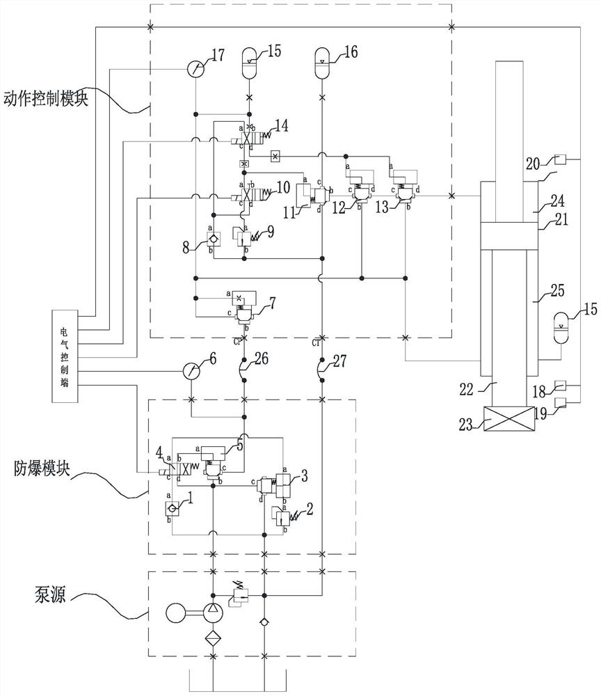
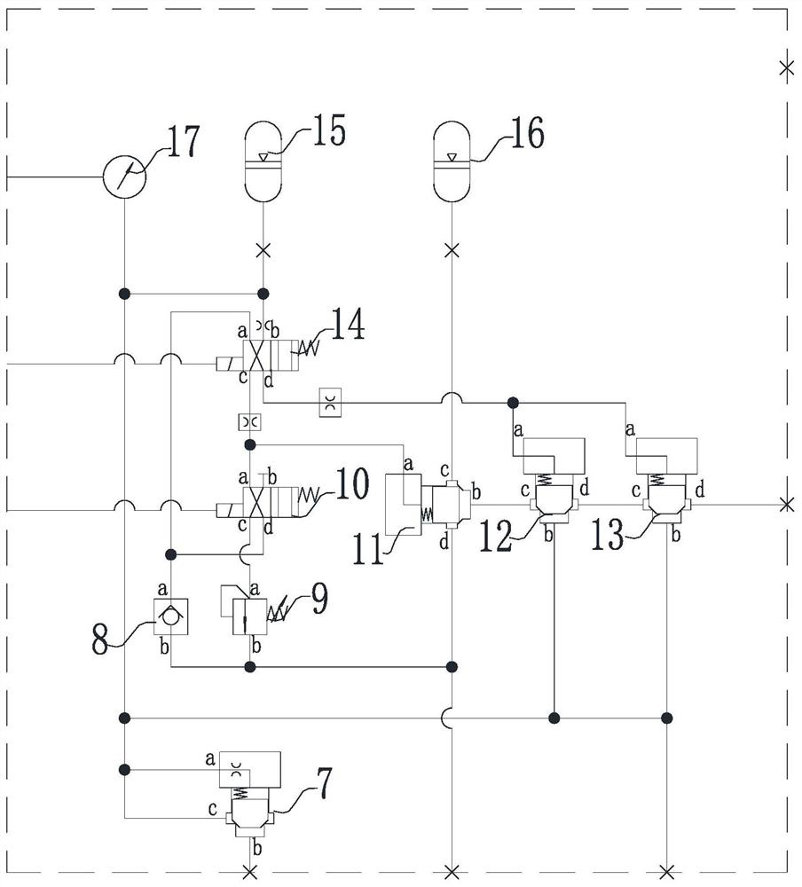
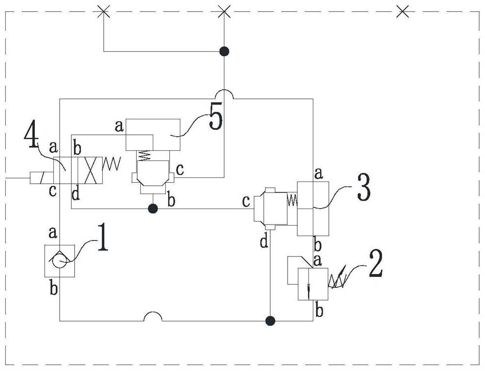
[0047] Such as Figure 1-6 As shown, an explosion-proof high-efficiency hydraulic piling hammer control system includes an electric control terminal, an oil cylinder assembly connected to the electric control end, and a pile hammer 23. The oil cylinder assembly includes an oil cylinder 21 and an action control syste...


PUM


Abstract

The invention relates to an explosion-proof high-efficiency hydraulic piling hammer control system and a piling method thereof. The system comprises an electrical control terminal, a pump source and ahydraulic piling hammer module, wherein the pump source and the hydraulic piling hammer module are connected with the electrical control terminal, the hydraulic piling module comprises a hydraulic cylinder, a piston rod movably arranged in the hydraulic cylinder and a piling hammer fixedly connected with the bottom of the piston rod, and an explosion-proof module and an action control module arefurther included. By utilizing special design, the system is efficient, saves energy, prevents explosion and has high safety in the piling process.

Description

technical field [0001] The invention relates to the technical field of hydraulic piling, in particular to an explosion-proof high-efficiency hydraulic piling hammer control system and a piling method thereof. Background technique [0002] With the development of science and the wide application of hydraulic piling technology, people's requirements for hydraulic piling technology have gradually become higher. The hydraulic piling technology on the market can no longer meet the actual application and the requirements of customers. The existing hydraulic piling hammer has The following major disadvantages: [0003] First, the control efficiency is low. Due to the complex control system of the hydraulic pile driver, a combination of various valve actions is used to meet the control requirements, and there is a sequence of actions between the valves, resulting in a lag in response during control, which affects the pile driver. Work efficiency: In the process of reversing control...

Claims


Application Information

Patent Timeline
IPC IPC(8): F15B11/08F15B11/04F15B20/00F15B21/14F15B1/027E02D7/06E02D7/14
CPCE02D7/06E02D7/14F15B1/027F15B11/04F15B11/08F15B20/005F15B20/007F15B21/14F15B2211/212F15B2211/865
Inventor 郭晓春
Owner 无锡市汉为液压气动有限公司
Learn More