Straw smashing and returning residual film recycling bundling machine

A technology for recycling residual film and crushing straw, which is applied to collectors, harvesters, agricultural machinery and implements, etc., and can solve problems such as unclean removal, white pollution, and high cotton straw

Inactive Publication Date: 2021-03-16
唐露苗
View PDF0 Cites 1 Cited by
  • Summary
  • Abstract
  • Description
  • Claims
  • Application Information

AI Technical Summary

Problems solved by technology

[0002] Plastic film mulching is a measure to cover the surface with agricultural plastic film. It can reduce the impact of raindrops and prevent erosion and crust formation. It can effectively reduce the evaporation of soil moisture, protect moisture in drought, increase moisture after rain, and promote crops The absorption and growth of water can improve the utilization efficiency of soil water. However, the main disadvantage of plastic film mulching technology is that after the crops are recycled, the plastic film remains on the land, which is not clean, causing serious white pollution. At the same time, a large amount of residues in the soil The accumulation of film year by year will affect the air permeability of the soil, hinder the movement of soil water and fertilizer, affect the growth and development of the root system of crops, cause crops to die, reduce production and other problems
[0003] Residual mulch film is a kind of white pollution. It is very difficult to recycle the residual mulch film in the cotton field. The reasons are: the cotton stalks are thick, and it takes a lot of manpower or mechanical power to uproot them; the cotton stalks are high, and the residual film recycling is difficult. , Cotton farmers need a lot of manpower to remove it manually; due to the unevenness of the field, the length of the straw is different when it is cut, and the longer straw will affect the recovery of the plastic film

Method used

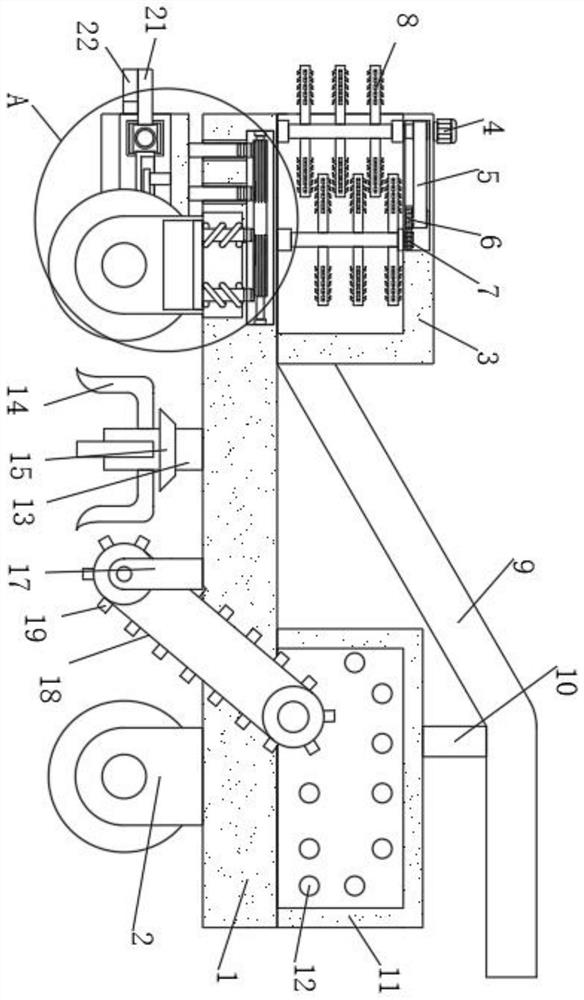
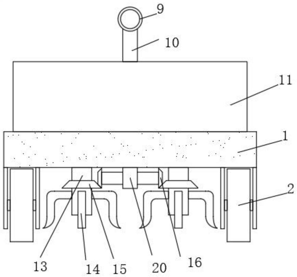
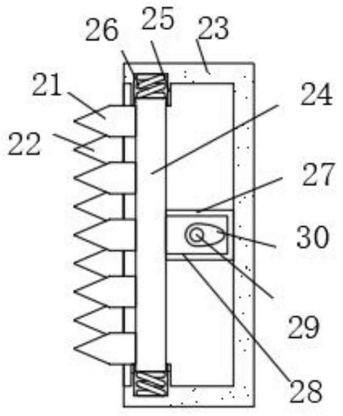

Image

  • Straw smashing and returning residual film recycling bundling machine
  • Straw smashing and returning residual film recycling bundling machine
  • Straw smashing and returning residual film recycling bundling machine

Examples


Embodiment Construction

[0027] The following will clearly and completely describe the technical solutions in the embodiments of the present invention with reference to the accompanying drawings in the embodiments of the present invention. Obviously, the described embodiments are only some, not all, embodiments of the present invention.

[0028] In describing the present invention, it should be understood that the terms "center", "longitudinal", "transverse", "length", "width", "thickness", "upper", "lower", "front", " Orientation or position indicated by "back", "left", "right", "vertical", "horizontal", "top", "bottom", "inner", "outer", "clockwise", "counterclockwise", etc. The relationship is based on the orientation or positional relationship shown in the drawings, and is only for the convenience of describing the present invention and simplifying the description, rather than indicating or implying that the referred device or element must have a specific orientation, be constructed and operated in...


PUM


Abstract

The invention discloses a straw smashing and returning residual film recycling bundling machine. The machine comprises a base and two mounting frames, the two mounting frames are fixedly connected tothe lower side of the base, walking wheels are rotatably connected to the two mounting frames, a smashing box is fixedly connected to the upper side of the base, and a smashing assembly is arranged atthe inner side of the smashing box; and two first connecting rods are connected to the base in a sliding manner, the two first connecting rods are jointly and fixedly connected with a shell, a cutting assembly is arranged on the shell, and a recycling assembly is arranged at the lower side of the base. The machine is reasonable in design, when the walking wheels run to low-lying positions, sliding blocks move downwards under the inertia effect, the sliding blocks drive the shell to move upwards through the first connecting rods, a transmission gear and second connecting rods, and the purposethat even if the base moves downwards, the height of the shell cannot be decreased accordingly is achieved; and therefore, after the straw is cut, a large height difference does not occur, and recycling of a mulching film is not affected.

Description

technical field [0001] The invention relates to the technical field of bundling machines, in particular to a bundling machine for recovering residual film after crushing straw and returning to the field. Background technique [0002] Plastic film mulching is a measure to cover the surface with agricultural plastic film. It can reduce the impact of raindrops and prevent erosion and crust formation. It can effectively reduce the evaporation of soil moisture, protect moisture in drought, increase moisture after rain, and promote crops The absorption and growth of water can improve the utilization efficiency of soil water. However, the main disadvantage of plastic film mulching technology is that after the crops are recycled, the plastic film remains on the land, which is not clean, causing serious white pollution. At the same time, a large amount of residues in the soil The accumulation of film year by year will affect the air permeability of the soil, hinder the migration of s...

Claims


Application Information

Patent Timeline
Patent Type & Authority Applications(China)
IPC IPC(8): A01D43/08A01B43/00A01D43/12
CPCA01B43/00A01D43/08A01D43/12
Inventor 唐露苗姜斌
Owner 唐露苗
Why Eureka
Try Eureka