Machining device
A processing device and processing shaft technology, which is applied to grinding devices, grinding drive devices, metal processing equipment, etc., can solve the problems of damage to the processing device and the reduction of processing accuracy, so as to avoid temperature rise and adverse effects.
- Summary
- Abstract
- Description
- Claims
- Application Information
AI Technical Summary
Problems solved by technology
Method used
Image

Examples
Embodiment 1
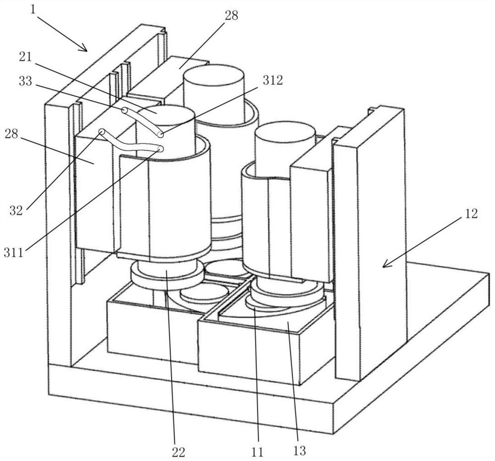
[0030] Next, refer to the attached Figure 1~3 Embodiment 1 of the processing apparatus 1 of this invention is demonstrated.
[0031] The processing apparatus 1 of the present embodiment performs polishing processing on a surface to be polished of a wafer so as to planarize the surface to be polished with high precision.
[0032] A wafer is a processing object of the processing apparatus 1 . In this embodiment, the wafer may be a semiconductor wafer with silicon, sapphire, gallium, etc. as the base material.
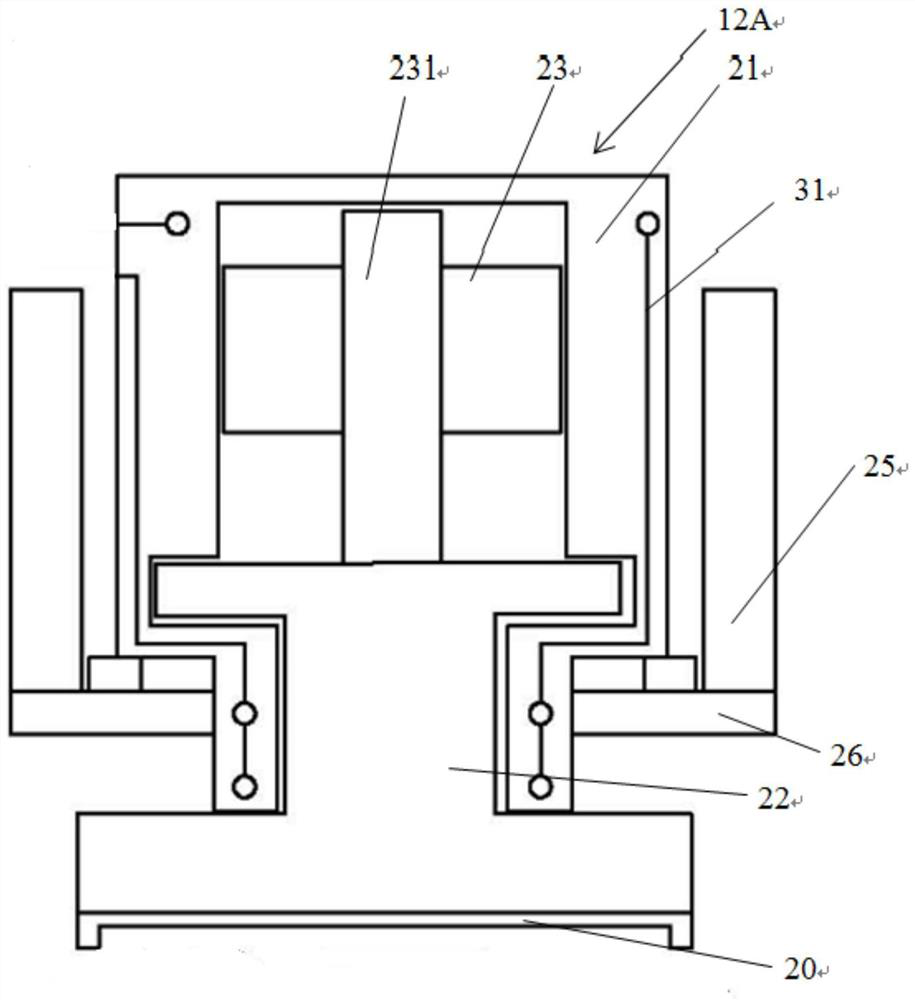
[0033] figure 1 is a perspective view showing the structure of the processing device 1 of the present invention, figure 2 It is a sectional view showing the machining shaft 12 of the machining apparatus 1 of the present invention.
[0034] Such as figure 1 , 2 As shown, the processing device 1 has a chuck 11, which is used to hold a wafer (not shown); and 3 processing axes 12; each processing axis 12 includes: a grinding pad 20, which performs grinding processin...
Embodiment 2
[0044] The processing apparatus of Example 2 differs from Example 1 only in the control unit, and descriptions of other components are omitted.
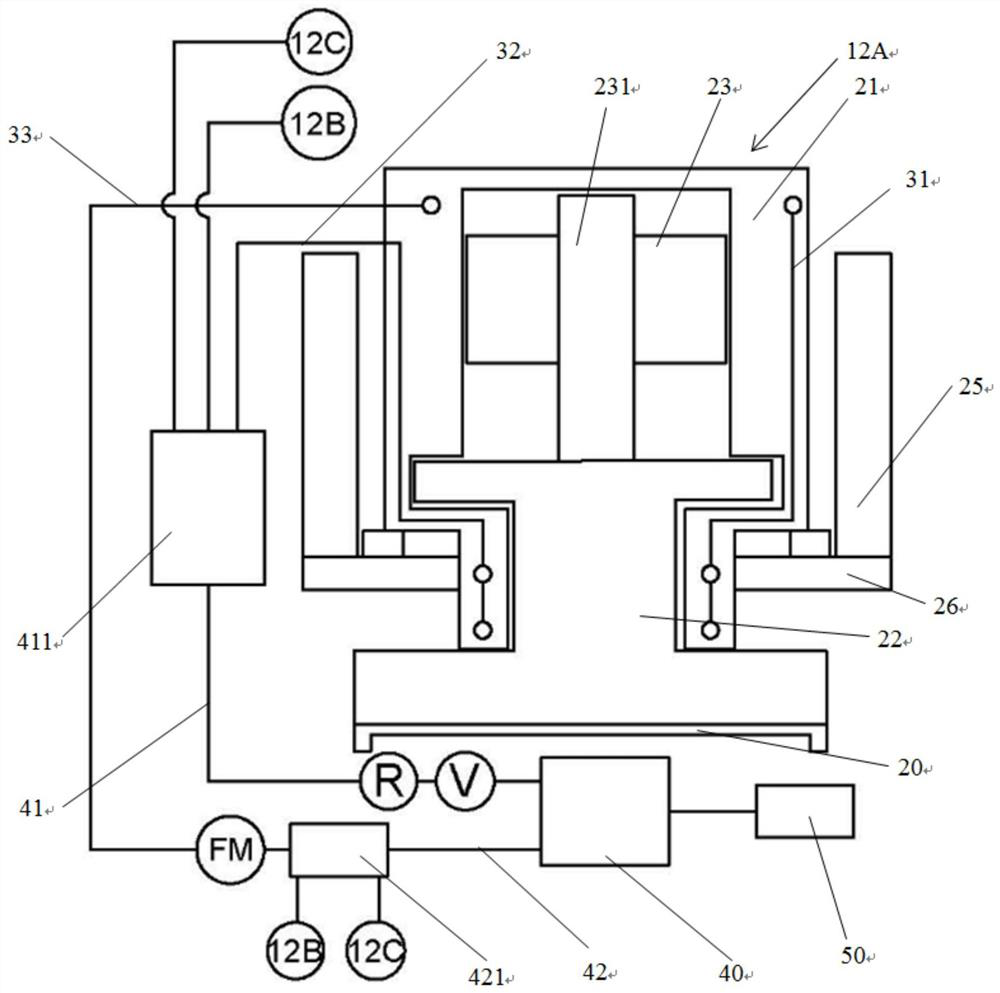
[0045] In Embodiment 1, the control unit controls the rotation operation of the spindle motor 23 based on the flow rate signal input from the flow rate detector FM. However, in the second embodiment, in addition to controlling the rotational operation of the spindle motor 23, the control unit also controls the lifting operation of the lifting mechanism 28 based on the flow rate signal input from the flow rate detector FM. When the flow rate of the cooling fluid detected by the flow rate detector FM is below a predetermined value (2 L / min in this embodiment), the control unit also sends a notification to the lift drive control unit (not shown) for controlling the lift mechanism 28. By sending a signal to raise the elevating mechanism 28 , the elevating drive control unit raises the elevating mechanism 28 to separate the polishing pad ...
Embodiment 3
[0048] The processing apparatus of Example 3 differs from Example 1 only in the position of the flow rate detector FM, and description of other components is omitted.
[0049] In Embodiment 3, the flow detector FM is arranged in the supply main pipe 41 , that is, the flow detector FM is located between the supply branch 411 and the cooler 40 . When the flow rate of the cooling fluid detected by the flow rate detector FM is below a predetermined value, the rotation of all the spindle motors 23 is stopped to stop the rotation of all the spindle motors 22 .
[0050] According to the processing apparatus of Example 3, since the flow rate can be detected by one flow rate detector FM, cost can be reduced.
[0051] other cases
[0052] In addition, in the above-mentioned embodiments, the grinding pad 20 is used as the processing part, but other components such as grinding wheels may also be used as needed.
[0053] In addition, in each of the above-mentioned embodiments, the proces...
PUM
 Abstract
Description
Claims
Application Information
 - Generate Ideas
- Intellectual Property
- Life Sciences
- Materials
- Tech Scout
- Unparalleled Data Quality
- Higher Quality Content
- 60% Fewer Hallucinations
Browse by: Latest US Patents, China's latest patents, Technical Efficacy Thesaurus, Application Domain, Technology Topic, Popular Technical Reports.
© 2025 PatSnap. All rights reserved.Legal|Privacy policy|Modern Slavery Act Transparency Statement|Sitemap|About US| Contact US: help@patsnap.com