Supercharge Your Innovation With Domain-Expert AI Agents!

Detection feedback device based on BIM model

A detection feedback and model technology, which is applied in the field of detection feedback devices based on BIM models, can solve the problems of less data obtained, bottlenecks in data collection and feedback, and long railway lines, and achieve the effect of improving detection range, data efficiency, and speed.

Active Publication Date: 2021-03-16
BINZHOU POLYTECHNIC
View PDF40 Cites 0 Cited by
  • Summary
  • Abstract
  • Description
  • Claims
  • Application Information

AI Technical Summary

Problems solved by technology

[0006] In the existing technologies combining BIM and railways, most of the BIM models are established in the initial stage (before the start of construction), and in the later stage of construction, acceptance and even operation, it is difficult to realize it only by manual work because the railway line is too long. The bottleneck of data collection and feedback,
[0007] However, in the specific construction process, it is inevitable that there is a certain discrepancy with the model components. Without the detection and feedback of real data, the opportunity for adjustment will be lost
At the same time, in operation, with the use of the surface of the rail, there will be obvious depressions (frequent braking and deceleration positions, etc.), so the existing maintenance requirements are also to regularly check the straightness, but under the existing conditions and technology, it is necessary to use artificial on-site The measurement can only be carried out for individual road sections. Not only is there very little data obtained, which is not enough to match the data support basis for the management of the entire railway model, but the accuracy is also limited by the level of the operator, and there are large fluctuations. Both the quantity and quality of data are difficult to support the continuous maintenance of the BIM model
As a result, BIM cannot truly perform its functions

Method used


Image

  • Detection feedback device based on BIM model
  • Detection feedback device based on BIM model
  • Detection feedback device based on BIM model

Examples


Embodiment Construction

[0042] Below in conjunction with specific embodiment, further illustrate the present invention. It should be understood that these examples are only used to illustrate the present invention and are not intended to limit the scope of the present invention. In addition, it should be understood that after reading the content taught by the present invention, those skilled in the art may make various changes or modifications to the present invention, and these equivalent forms also fall within the scope defined in the present application.

[0043] The instruments, reagents, materials, etc. involved in the following examples, unless otherwise specified, are conventional instruments, reagents, materials, etc. in the prior art, and can be obtained through formal commercial channels. The experimental methods, detection methods, etc. involved in the following examples, unless otherwise specified, are conventional experimental methods, detection methods, etc. in the prior art.

[0044] ...


PUM


Abstract

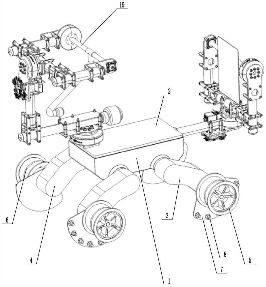
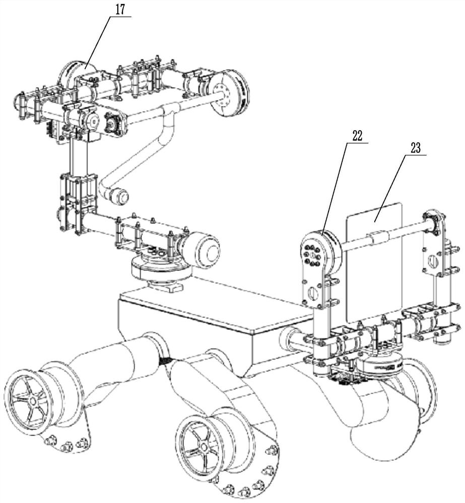
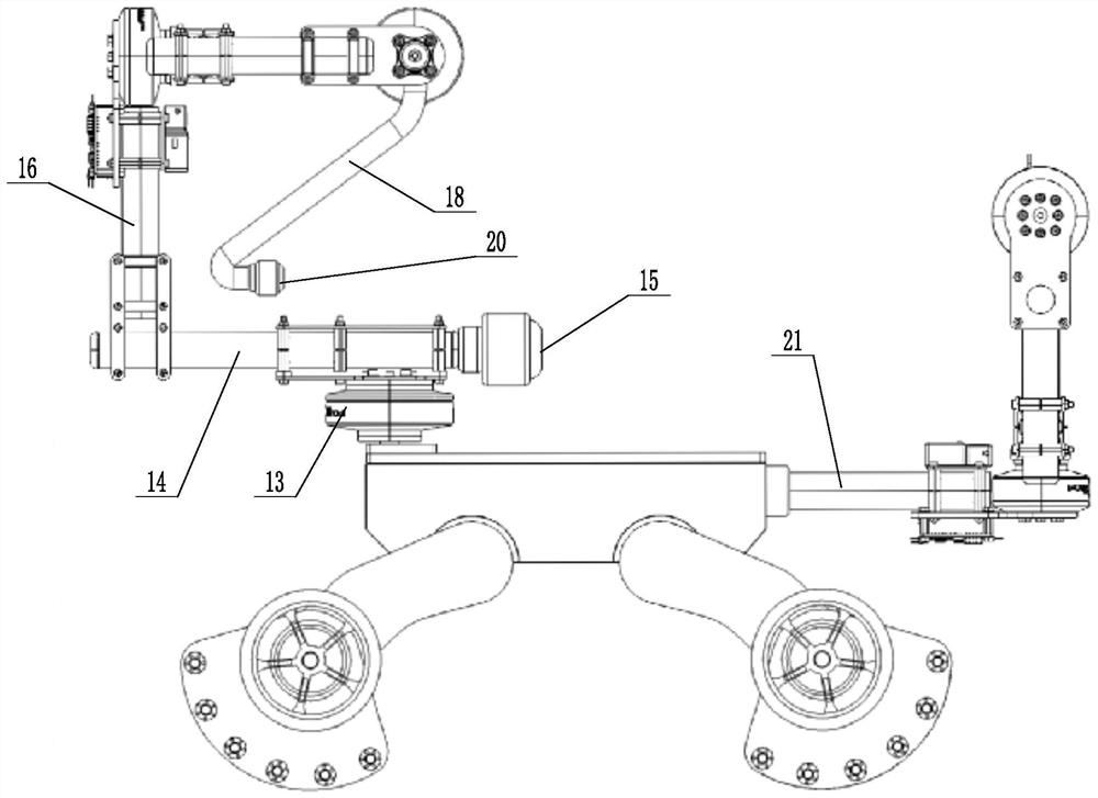
The invention discloses a detection feedback device based on a BIM model, and mainly relates to the technical field of BIM. The system comprises an advancing module, a transmitting module and a measuring module, wherein the advancing module is used for advancing along a rail at a constant speed, the transmitting module is installed on the advancing module and includes a first laser transmitter fixed to the advancing module and a second laser transmitter installed through a rear cradle head, and the measuring module is installed on the advancing module and located in front of the transmitting module. A laser signal capturing plate is installed through a front cradle head, and the laser signal capturing plate is used for capturing a first laser signal and a second laser signal transmitted bythe transmitting module. The device has the advantages that end surface condition detection and data acquisition of a rail line can be completed in a full-automatic mode, and high-efficiency, high-precision and high-coverage rail end fluctuation condition data is obtained.

Description

technical field [0001] The invention relates to the technical field of BIM, in particular to a detection and feedback device based on a BIM model. Background technique [0002] BIM (Building Information Modeling) refers to the process, method and technology of creating and using information models to manage and optimize the whole process of engineering project design, construction and operation and maintenance. [0003] The information model based on BIM technology can realize engineering virtual design, visual decision-making, collaborative construction, and transparent management, which will greatly improve the level of engineering decision-making, planning, survey, design, construction, and operation management, reduce errors, shorten Improve project quality and investment efficiency. [0004] The railway project has huge investment, many specialties, complex technology, long construction period and many participants. The application of BIM in railways is very important...

Claims


Application Information

Patent Timeline
IPC IPC(8): E01B35/04G01B11/27G06F30/13
CPCE01B35/04G01B11/27G06F30/13
Inventor 张秀燕周松孙金芳张晓霖丁友平赵霞
Owner BINZHOU POLYTECHNIC
Features
  • R&D
  • Intellectual Property
  • Life Sciences
  • Materials
  • Tech Scout
  • Unparalleled Data Quality
  • Higher Quality Content
  • 60% Fewer Hallucinations
Learn More