
Thermal and electrical power transformer

A transformer and thermoelectric technology, applied in the field of thermoelectric power generation, can solve problems such as low efficiency, failure to operate, power loss of electric drive pumps, etc.

Inactive Publication Date: 2021-03-16
谢尔格伊根纳季叶维奇巴亚金
View PDF4 Cites 0 Cited by
  • Summary
  • Abstract
  • Description
  • Claims
  • Application Information

AI Technical Summary

Problems solved by technology

[0012] Disadvantages of this device are: it cannot be run in heat pump mode, there is a loss of power required to drive the pump (compressor) electrically, and therefore it is inefficient

Method used


Image

  • Thermal and electrical power transformer

Examples


Embodiment Construction

[0021] The present invention is described in detail below in conjunction with specific embodiments.

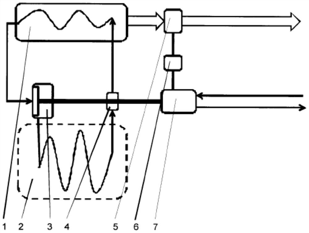
[0022] according to figure 1 As shown, this embodiment provides a thermoelectric transformer, which includes: an evaporator 2, a capacitor 1, a compressor 4, a throttle valve 3, a thermal power regulator 5, a motor generator 7, and a controller 6;

[0023] The user determines the amount of thermal power consumed by adjusting the thermal power regulator 5 . Working fluid is in the evaporator 2 of heat source temperature (ground, water, air). The controller 6 controls the motor generator 7, and the motor generator 7 is coaxially connected with the compressor 4, and the compressor 4 pumps the working fluid from the evaporator 2 to the capacitor 1. By increasing the pressure, the working fluid is heated, and the heat is transferred from the capacitor 1 to the thermal power utilization device through the thermal power regulator 5 . When the high-temperature working medium conti...


PUM


Abstract

The invention relates to the field of energy production, particularly to thermal and electrical power generation. The essence of the invention consists in that a device provides for the cogeneration of thermal and electrical power by means of low-temperature sources such as water, air, soil, and solar radiation, for the purposes of which a thermal energy supply regulator, a controller, and a generator / electric motor are additionally provided in a heat pump, wherein an input of the generator / electric motor is connected to an electrical energy source and an output is connected to an electrical energy load, a generator / motor control channel is connected to the controller, a second control channel of which is connected to the thermal energy supply regulator, an inlet of the regulator is connected to a condenser and an outlet is connected to a thermal energy load, moreover, a throttle is in the form of a turbine nozzle, a shaft of said turbine is connected to a shaft of a compressor, and ashaft of the compressor is connected to a shaft of the generator / electric motor. The structural design of the device allows for generating thermal and electrical power depending on proportions set bya load. The coefficient of performance (COP) of the device operates in the heat pump mode is improved, the size and material capacity are reduced, and vibration level is decreased.

Description

technical field [0001] The invention is applicable to the field of energy, especially thermoelectric power generation. Background technique [0002] Heat pumps are known and widely used heat pumps that utilize heat from a low-temperature heat source - water, air, soil, solar radiation - into a facility suitable for heating residential and industrial premises. [0003] The disadvantage of these devices is the low COP coefficient for the conversion of electrical power to thermal power. The COP coefficient shows how many times the amount of thermal power delivered to a consumer is the electricity required to transfer thermal power from a low-temperature heat source to a high-temperature consumer. The actual efficiency values ​​of modern heat pumps are COP = 2.0 at source temperature (evaporator) -20°C and COP = 4.0 at source temperature +7°C. [0004] Known methods and apparatus convert thermal energy from a low-temperature heat source into electrical energy. The closest thi...

Claims


Application Information

Patent Timeline
Patent Type & Authority Applications(China)
IPC IPC(8): F02G1/043F03G7/06F25B11/02
CPCF02G1/043F03G7/06F25B11/02Y02E10/46F03G7/047F03G4/02F03G4/029F03G4/033F03G4/045F03G6/092F03G6/004F25B29/00F03G6/0055
Inventor 谢尔格伊·根纳季叶维奇·巴亚金维克托罗维奇·安德列伊·加夫里科夫
Owner 谢尔格伊根纳季叶维奇巴亚金
Learn More