
Turbomachine

A technology of turbines and turbine casings, applied in the lubrication of turbine/propulsion devices, mechanical equipment, engine components, etc., can solve problems such as damage to turbine efficiency, increase thermal friction loss of impellers, etc., to achieve the effect of improving working methods

Active Publication Date: 2021-03-16
ROBERT BOSCH GMBH
View PDF11 Cites 0 Cited by
  • Summary
  • Abstract
  • Description
  • Claims
  • Application Information

AI Technical Summary

Problems solved by technology

However, the bearings on both sides increase the thermal friction loss on the impeller, thereby compromising the efficiency of the turbine

Method used


Image

  • Turbomachine
  • Turbomachine
  • Turbomachine

Examples


Embodiment Construction

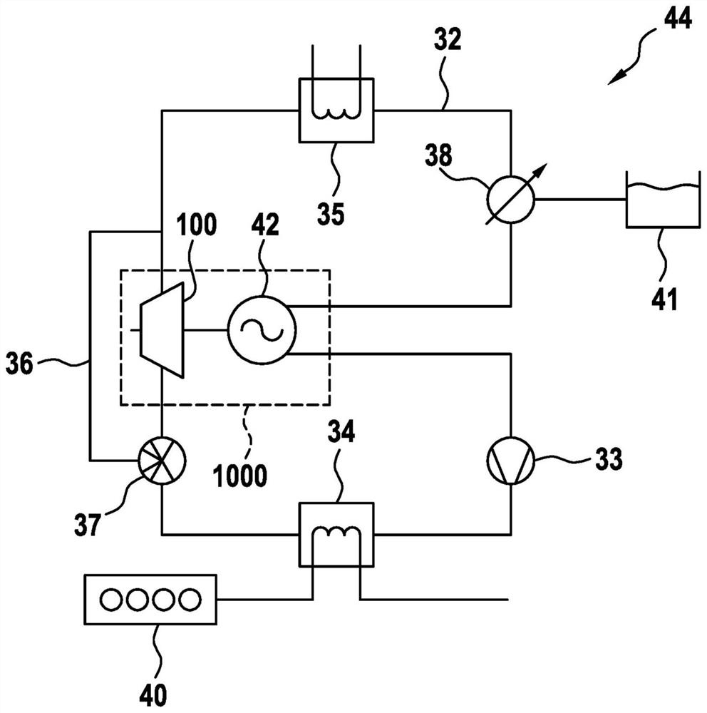
[0025] figure 1 The known waste heat recovery system 44 of the internal combustion engine 40 is shown schematically, wherein only the main region is shown.

[0026] The waste heat recovery system 44 has a circuit 32 that directs the working medium, and the circuit includes a fluid pump 33, an evaporator 34, a turbine 100, and a condenser 35 in the flow direction of the working medium. Here, the condenser 35 can, for example, be coupled to the cooling system of the internal combustion engine 40.

[0027] The bypass line 36 is connected in parallel with the turbine 100. The mass stream of the working medium can be assigned to the turbine 100 and / or bypass line 36 by the bypass valve 37 as needed.

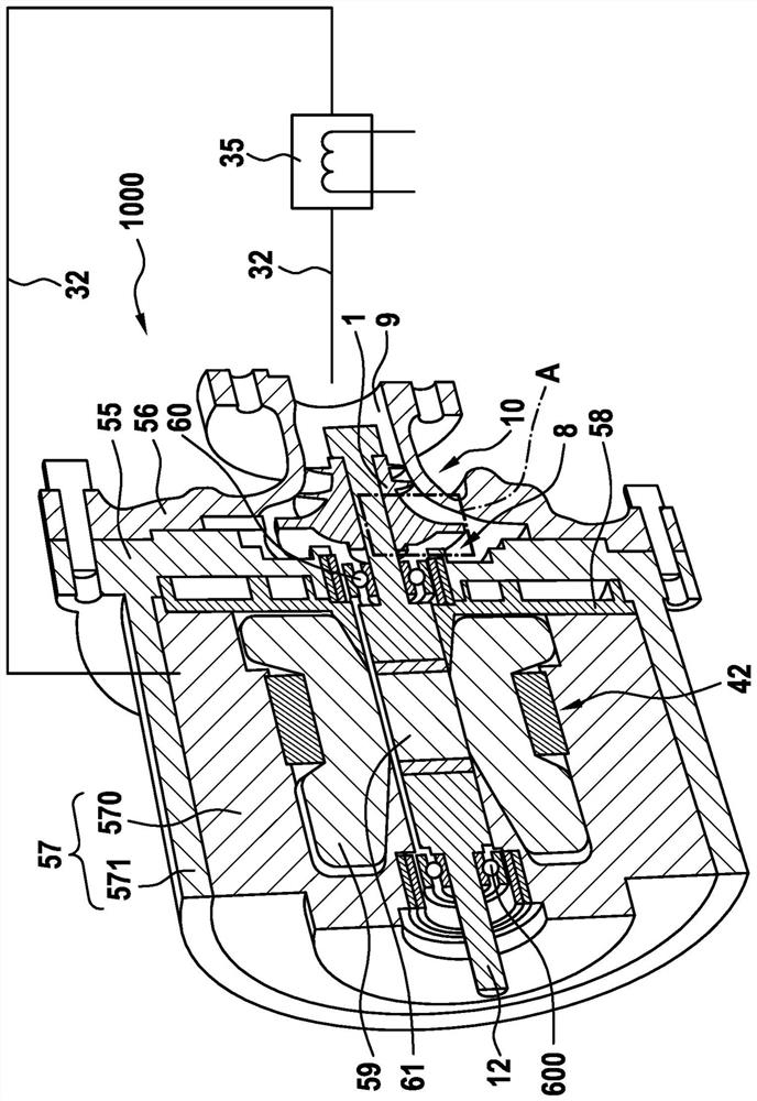
[0028] Here, the turbine 100 is part of the turbine unit 1000. The turbine unit 1000 additionally includes a generator 42, in addition, optionally also include bypass valve 37 and bypass line 36. The generator 42 converts the mechanical energy generated in the turbine 100 into electri...


PUM


Abstract

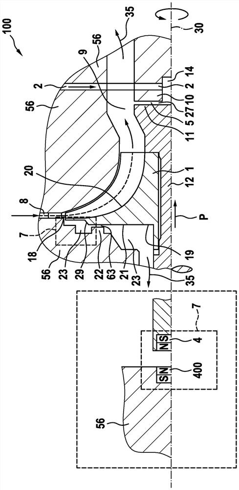
The invention relates to a turbomachine (100) having a turbo housing (56) and an impeller (1) which is mounted such that it can be moved about a rotational axis (30), which impeller (1) defines an inflow region (8) and an outflow region (9) of a working medium on a front side (20). The impeller (1) is operatively connected to a shaft (12). Furthermore, together with the turbo housing (56), the impeller (1) or the shaft (12) configures an axial bearing (27) which is embodied as a gas bearing, wherein the impeller (1) or the shaft (12) is prestressed in the direction of the axial bearing (27) byway of a prestressing means (7).

Description

Technical field [0001] The present invention relates to a turbine that can be used, for example, in a waste heat recovery system for a waste heat used for an internal combustion engine or a compressor for a fuel cell system. Background technique [0002] An turbine for a waste heat recovery system for an internal combustion engine is described, for example, a turbine for an internal combustion engine. The turbine has a housing that is arranged in the housing having an impeller arranged on the drive shaft. In addition, the turbine has an inflow region and an outflow region, wherein the turbine flows through the working medium during operation. The working medium flows along the front side of the impeller flows into the inflow region of the turbine. Here, there is a pressure drop between the inflow region and the outflow region. Further, in the turbine, a voltage divider is arranged near the back side of the impeller. Therefore, the pressure acting on the back side of the impeller ...

Claims


Application Information

Patent Timeline
IPC IPC(8): F04D29/051F01D5/04F01D25/16F01D25/22F02C7/06
CPCF05D2240/52F05D2240/51F01D5/043F01D25/168F01D25/22F05D2220/40F02C7/06F04D29/051Y02E60/50
Inventor A·什蒂尔班M·德赖茨勒G·戴默I·L·耶普雷J·特劳特曼F·弗尔斯特M·迈尔
Owner ROBERT BOSCH GMBH
Learn More