Scramjet self-adaptive perforation fluctuation fracturing synergy system

A self-adaptive and fracturing technology, applied in the direction of mining fluid, earthwork drilling, explosives, etc., can solve the problems of high energy, casing damage, wellbore and formation damage, etc.

Pending Publication Date: 2021-03-19
山东北方民爆器材有限公司
View PDF0 Cites 4 Cited by
  • Summary
  • Abstract
  • Description
  • Claims
  • Application Information

AI Technical Summary

Problems solved by technology

But there are several disadvantages in this technical scheme, the first is that the work efficiency is low
The longitudinal distance between the fracturing agent and the perforation hole is large, and the pressure generated by the secondary deflagration of the fracturing agent is difficult to directly act on the formation channel, and the work efficiency is low
The second is that there are many charges and high energy, and there is a risk of sleeve damage
However, this technology has the following disadvantages. First, during the lowering process of the perforating device, the inner wall of the casing sometimes scratches the jacketed grain, which may easily cause premature deflagration of the grain and cause downhole accidents.
Second, the direct impact and erosion of high-pressure gas on the wellbore will also cause a certain degree of damage to the wellbore and formation
The disadvantages are that the perforation tunnel reconstruction ability is weak, the pressure load continuity is poor, the deflagration reaction is incomplete, and the degree of formation fracturing stimulation is limited.

Method used


Image

  • Scramjet self-adaptive perforation fluctuation fracturing synergy system
  • Scramjet self-adaptive perforation fluctuation fracturing synergy system
  • Scramjet self-adaptive perforation fluctuation fracturing synergy system

Examples


Embodiment 1

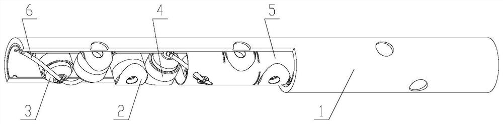
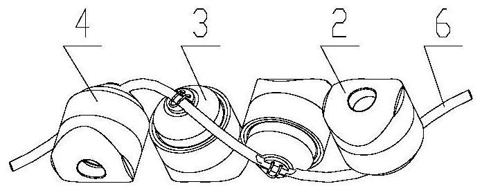
[0112] Such as Figure 6-Figure 11 As shown: the scram adaptive energy-releasing perforating charge 3 sequentially includes an adaptive active metal charge cover 301, an explosive charge column 302, and a double-layer energetic shell 303 from the inside to the outside, and the outer shell of the double-layer energetic shell 303 The body 30301 is a carbon steel shell, and the inner layer is an energetic material layer 30302 . The double-layer energetic shell 303 includes an integral hollow cylindrical section and a hollow frustum of a cone, the upper end of which is open, and the self-adaptive active metal drug cover 301 is a conical cover, the bottom of which is fixed on the cylindrical section of the double-layer energetic shell On the lower inner wall of the cylinder section, the lower end of the cylindrical section is sealed, and the explosive grain column 302 is located in the cavity between the self-adaptive active metal powder cover 301 and the double-layer energetic she...

Embodiment 2

[0126] The structure of each module in this embodiment is the same as that in Embodiment 1.

[0127] An oil well is taken as an example below to describe the application of this embodiment in detail.

[0128] A certain oil well has a depth of 3400m, oil and gas layer thickness of 50m, and reservoir location: 2980.2-3030.2m, belonging to tight gas sandstone. Since this well section is developed with low porosity and permeability, the drilling mud pollutes the near-wellbore area during the drilling process. Through detailed analysis and demonstration by the construction department, it is believed that conventional perforation methods cannot effectively open the polluted reservoir. Supporting equipment and on-site construction conditions are limited, and new perforation efficiency enhancement technology needs to be adopted. Through technical comparison and on-site construction period requirements, the super-combustion self-adaptive perforation efficiency enhancement technology is...

Embodiment 3

[0138] The structure of each module in this embodiment is the same as that in Embodiment 1.

[0139] The application of this embodiment will be described in detail below by taking a water injection well of an oil factory as an example.

[0140] The water injection well of an oil factory has a depth of 1400m and a water injection interval of 650m to 680m, which is a transfer injection well. Since the well could not be effectively injected before, it is still in a shutdown state.

[0141] Considering the complex geological structure and tight formation in the area where the oil well is located, the super-combustion wave pulse perforation technology scheme was optimally designed, and the material selection was optimized through the system. The relevant design components and mass percentages of Example 3 are as follows:

[0142] The components and mass percentages of the self-adaptive active metal charge 301 of the scram self-adaptive energy release charge 3 are: copper 25%; tungst...


PUM

PropertyMeasurementUnit
thicknessaaaaaaaaaa

Abstract

The invention particularly relates to a scramjet self-adaptive perforation fluctuation fracturing synergy system. The system is characterized by comprising a scramjet perforation system tubular column, a scramjet series charging module, scramjet self-adaptive energy-releasing perforating bullets, a scramjet energy-continuing charging module, a scramjet perforation system bullet carrier and a detonating cord, wherein the scramjet self-adaptive energy-releasing perforating bullets are installed in the scramjet perforating system bullet carrier, the scramjet series charging module is buckled at the opening position of a shaped charge liner of the scramjet self-adaptive energy-releasing perforating bullets, the scramjet energy-continuing charging module is fixed to the portion, around the scramjet self-adaptive energy-releasing perforating bullets, of the scramjet perforating system bullet carrier, the detonating cord is connected with all the scramjet self-adaptive energy-releasing perforating bullets, and the scramjet series charging module, the scramjet self-adaptive energy-releasing perforating bullets, the scramjet energy-continuing charging module, the scramjet perforating systembullet carrier and the detonating cord are combined into a whole and then loaded into the scramjet perforating system tubular column. Compared with a perforation technology of the same type, the system has an obvious stratum fracturing conduction effect.

Description

technical field [0001] The invention belongs to the technical field of oil and gas exploration and development, and in particular relates to a super-combustion self-adaptive perforation wave fracturing synergistic system. Background technique [0002] At present, oil and gas perforation technology is mainly divided into active perforating charge technology, composite perforation technology, split composite perforation technology and integrated composite perforation technology. [0003] Active Perforating Charge Technology [0004] Active energy perforating charge technology, also known as self-reactive liner perforating charge technology, is a development direction of energy-concentrated perforating technology. The main feature of this technology is that the liner used inside the perforating charge The drug column can react by itself during detonation. Under the action of high temperature and high pressure, the drug-shaped cover can not only form perforation, but also have ...

Claims


Application Information

Patent Timeline
Patent Type & Authority Applications(China)
IPC IPC(8): E21B43/116C22C9/00C22C9/06C22C30/02C22C32/00C06B33/02C06B33/12C06B33/06C08L33/12C08L55/02C08K3/36C08L81/02C08L81/06C08K5/20
CPCC06B33/02C06B33/06C06B33/12C08L33/12C08L81/02C22C9/00C22C9/06C22C30/02C22C32/00E21B43/116C08L55/02C08K3/36C08L81/06C08K5/20
Inventor 卢朝喜张会之盛庭强卢现飞贾双英韩早王建政杨阳马兆明曹海霞赵袁吉刘鹏程
Owner 山东北方民爆器材有限公司
Why Eureka
Try Eureka