Method for designing metal connecting wires in power device layout

A power device and metal wiring technology, which is applied in the design field of metal wiring in the layout of power devices, can solve problems such as differences in final results, weak electrical conduction performance, and affecting the performance of power devices.

Active Publication Date: 2021-03-23
SHENZHEN INJOINIC TECH
View PDF8 Cites 3 Cited by
  • Summary
  • Abstract
  • Description
  • Claims
  • Application Information

AI Technical Summary

Problems solved by technology

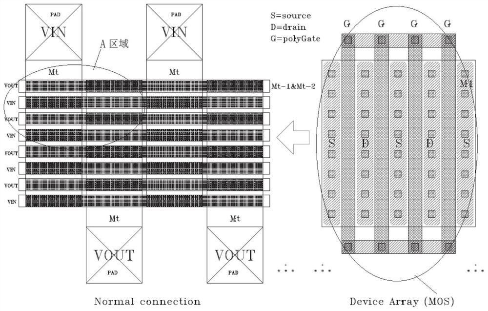
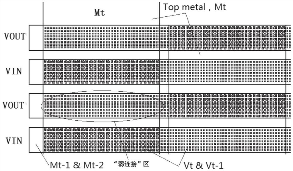
In this way, there will be a problem. When the top metal layer (Mt) is very wide and the signal is the input signal (VIN), the opposite signal output signal (VOUT) connection flowing through the second top metal layer (Mt-1) will form A "weak connection" area with a large span, which will cause the electrical conduction performance of ordinary metals to be much weaker than that of the top metal layer (Mt), so this will eventually lead to the flow through the power device array (Device Array) The current density of each channel is more and more uneven, which affects the overall performance of power devices
[0006] Therefore, in the layout design of power devices, in order to obtain the best working performance of power devices, metal layers of various layers often need to be used together at the same time, but in the process of using them together, different connection methods will also make the final result different. Therefore, designers urgently need to design an optimized method for metal interconnection of each layer of power device layout

Method used


Image

  • Method for designing metal connecting wires in power device layout
  • Method for designing metal connecting wires in power device layout
  • Method for designing metal connecting wires in power device layout

Examples


Embodiment Construction

[0031] In order to make the above objects, features and advantages of the present invention more comprehensible, specific implementations of the present invention will be described in detail below in conjunction with the accompanying drawings.

[0032] However, the present invention can be implemented in many other ways different from those described here, and those skilled in the art can make similar extensions without violating the connotation of the present invention, so the present invention is not limited by the specific implementations disclosed below. Secondly, the present invention is described in detail using schematic diagrams. When describing the embodiments of the present invention in detail, for the convenience of explanation, the cross-sectional view showing the device structure will not be partially enlarged according to the general scale, and the schematic diagram is only an example, and it should not be limited here. The protection scope of the present inventio...


PUM


Abstract

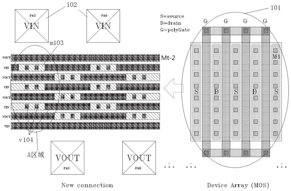
The invention provides a method for designing metal connecting wires in a power device layout, a power device comprises at least three layers of metal, in the design method, a secondary top metal layer Mt-1 can form a distribution structure similar to Slot under a top metal layer Mt representing opposite signals, so that signals represented by thesecondary top metal layer Mt-1 can be connected inboth the direction X and the direction Y, under the top metal layer Mt, the current on the third metal layer Mt-2 is directly connected and conducted to the top metal layer Mt through a contact hole Vt and a contact hole Vt-1, so that the connection and conduction capability of the secondary top metal layer Mt-1 in the layout is enhanced, and the reliability of the layout is improved. The difference between the conductivity of the secondary top metal layer Mt-1 and the conductivity of the top metal layer Mt in the layout connecting line is reduced, so that the current density distribution in the whole layout is more uniform, the on-resistance is reduced, the power consumption is reduced, and the efficiency is improved.

Description

【Technical field】 [0001] The invention relates to integrated circuit device technology, in particular to a design method for metal wiring in a power device layout. 【Background technique】 [0002] In the layout design of integrated circuits, the layout design of power devices is an important link. The quality of power device layout design often determines the performance of integrated circuits, and is the key factor determining the success or failure of integrated circuit design. The main indicators for evaluating the layout design of power devices include layout area utilization, noise isolation, on-resistance (Rdson), whether the metal line width on the current path meets the current requirements when the rated current passes through the power device, and whether the power device layout meets the current requirements. Whether the current density distribution in the power supply is uniform or not, these factors will affect the efficiency of the power device and even determin...

Claims


Application Information

Patent Timeline
Patent Type & Authority Applications(China)
IPC IPC(8): G06F30/394H01L23/528H01L27/02
CPCG06F30/394H01L27/0207H01L23/528Y02E60/00
Inventor 曾令宇
Owner SHENZHEN INJOINIC TECH
Why Eureka
Try Eureka