Moving contact bridge retaining structure of anti-short-circuit capability improving switch device

A technology of anti-short-circuit ability and switching device, which is applied in the direction of electric switches, contacts, circuits, etc., can solve the problems of poor anti-short-circuit ability and achieve the effect of consistent mechanical properties

Pending Publication Date: 2021-03-23
武汉同力同为科技有限公司
View PDF9 Cites 0 Cited by
  • Summary
  • Abstract
  • Description
  • Claims
  • Application Information

AI Technical Summary

Problems solved by technology

[0005] The purpose of the present invention is to overcome the above-mentioned technical deficiencies, and provide a moving contact bridge holding structure for improving the short-circuit resistance of the switch device, which is used to solve the problem of poor short-circuit resistance of the switch device in the prior art

Method used


Image

  • Moving contact bridge retaining structure of anti-short-circuit capability improving switch device
  • Moving contact bridge retaining structure of anti-short-circuit capability improving switch device
  • Moving contact bridge retaining structure of anti-short-circuit capability improving switch device

Examples


Embodiment 1

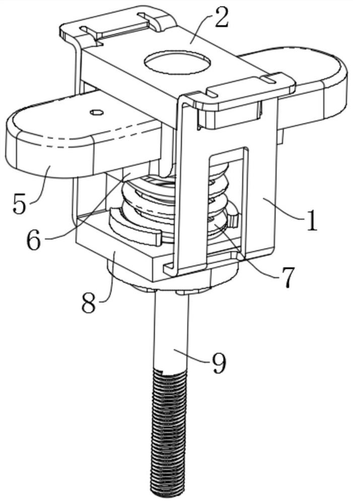
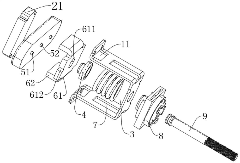
[0028] see figure 1 and figure 2 , the present embodiment provides a dynamic contact bridge holding structure for improving the short-circuit resistance of the switch device, which includes a cage 1, a top plate 2, a connecting piece 4, a moving touch bridge 5, a magnetic conductive component 6 and an elastic component 7, wherein:

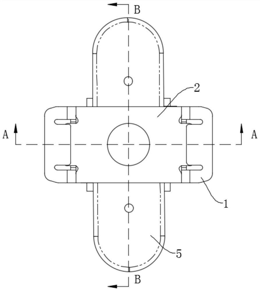
[0029] Both ends of the cage 1 and the top plate 2 are fixedly connected and enclosed to form a mounting opening 3 with both ends open, and the straight line where the opening direction of the mounting opening 3 is located is the first axis a.

[0030] The movable contact bridge 5 is disposed in the installation opening 3 along the first axis a and is in contact with the top plate 2 , and the movable contact bridge 5 is arranged between two static contacts.

[0031] The magnetically conductive part 6 is arranged in the installation port 3 and connected with the movable contact bridge 5. The magnetically conductive part 6 includes a resisting part...

Embodiment 2

[0039] see Figure 8 , Embodiment 2 is basically the same as Embodiment 1, and will not be repeated here. The difference is that: the first connecting part 41 and the moving contact bridge 5' are fixed by resistance welding. Specifically, the moving contact bridge 5' After assembling correspondingly with the magnetic guide 6, put the connecting piece 4' into the installation hole 611, apply a certain pressure to the first connecting part 41 and the moving contact bridge 5' and weld them together, this process does not need to process the corresponding riveting mouth and riveting structure, reducing manufacturing process.

[0040] The following is a detailed description of the working principle of the moving contact bridge holding structure of a switch device with improved short-circuit resistance provided by the present invention: when the magnetic circuit part is energized, a magnetic field is generated to drive the driving rod 9 and the cage 1 to move toward the static conta...


PUM


Abstract

The invention discloses a moving contact bridge retaining structure of an anti-short-circuit capability improving switch device, which comprises a retainer, a top plate, a connecting piece, a movablecontact bridge, a magnetic conductive piece and an elastic piece, and is characterized in that the retainer and the two ends of the top plate are fixedly connected and encircled to form a mounting port with two open ends, a first connecting part is arranged in a mounting hole and is fixedly connected with the movable contact bridge, the second connecting part is arranged around the outer side of the mounting hole and abuts against the side, which is away from the movable contact bridge, of the abutting part so as to apply force to the movable contact bridge to the abutting part. According to the invention, because the movable contact bridge and the magnetic conductive piece are connected and fixed by the connecting piece, the magnetic conductive piece can be well limited, so that the top plate and the magnetic conductive piece are attracted stably when a large current, such as a short-circuit current, occurs in a system loop. In addition, the magnetic conductive piece and the movable contact bridge can also be matched in the thickness direction without a clearance. When the movable contact bridges in the plurality of movable contact bridge structures are conducted with the static contact, the compression amount of each elastic piece is kept consistent so as to provide consistent mechanical properties.

Description

technical field [0001] The invention relates to the technical field of switch devices, in particular to a moving contact bridge holding structure of a switch device for improving short-circuit resistance. Background technique [0002] For the direct-acting magnetic circuit structure DC switchgear of the prior art, its interior is driven by the moving contact bridge and the static contact connected to the outside through the magnetic circuit system to realize the on and off functions. In the case of a short circuit, the contact area between the moving contact bridge and the static contact will generate an electric repulsion force, which will push the moving contact bridge away when the repulsion force is large enough, resulting in abnormal disconnection of the switch device, arcing, burning or even explosion. [0003] For the switchgear used in the current electric vehicle industry, due to the increasing energy of the battery system, this will require the short-circuit resist...

Claims


Application Information

Patent Timeline
Patent Type & Authority Applications(China)
IPC IPC(8): H01H1/20
CPCH01H1/20H01H1/2008
Inventor 不公告发明人
Owner 武汉同力同为科技有限公司
Why Eureka
Try Eureka