
A scr low temperature denitrification device

A low-temperature denitrification and catalyst technology, which is applied in separation methods, dispersed particle separation, chemical instruments and methods, etc., can solve the problems of catalyst agglomeration deactivation, low catalytic efficiency, insufficient cooling effect of adsorption, etc., to prolong the reaction time , the effect of improving the catalytic efficiency

Active Publication Date: 2021-12-21
YANCHENG LANFENG ENVIRONMENTAL ENG TECH
View PDF6 Cites 0 Cited by
  • Summary
  • Abstract
  • Description
  • Claims
  • Application Information

AI Technical Summary

Problems solved by technology

[0004] The purpose of the present invention is to provide a SCR low-temperature denitration device to solve the problems of easy agglomeration and deactivation of the catalyst in the denitration reactor, the adsorption of the catalyst to the flue gas, insufficient cooling effect, and low catalytic efficiency.

Method used


Image

  • A scr low temperature denitrification device
  • A scr low temperature denitrification device
  • A scr low temperature denitrification device

Examples


Embodiment 1

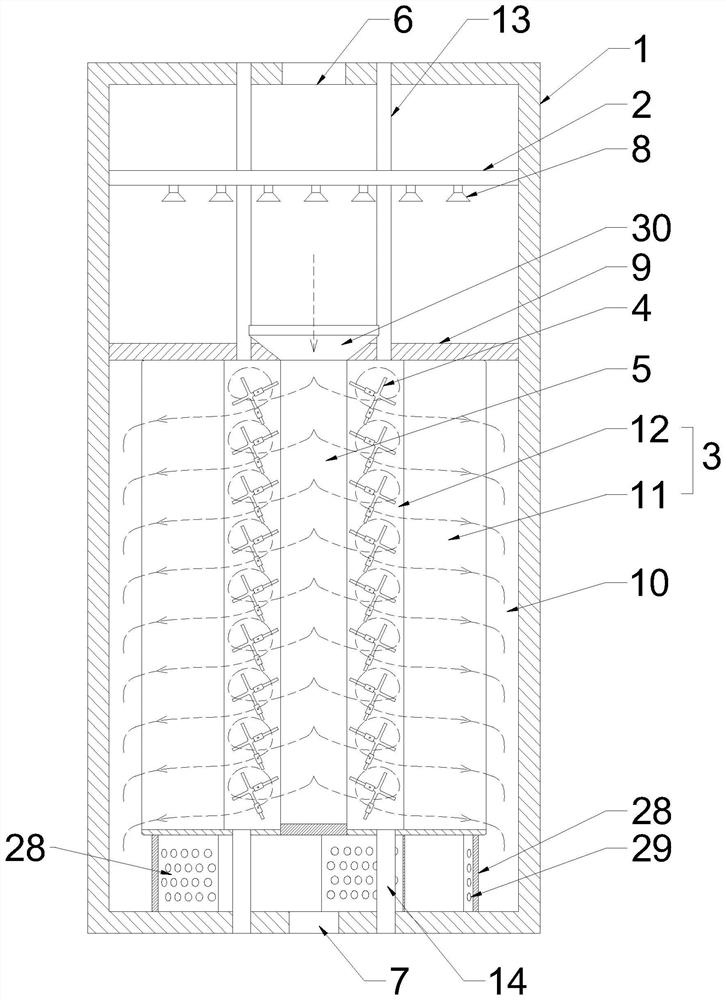
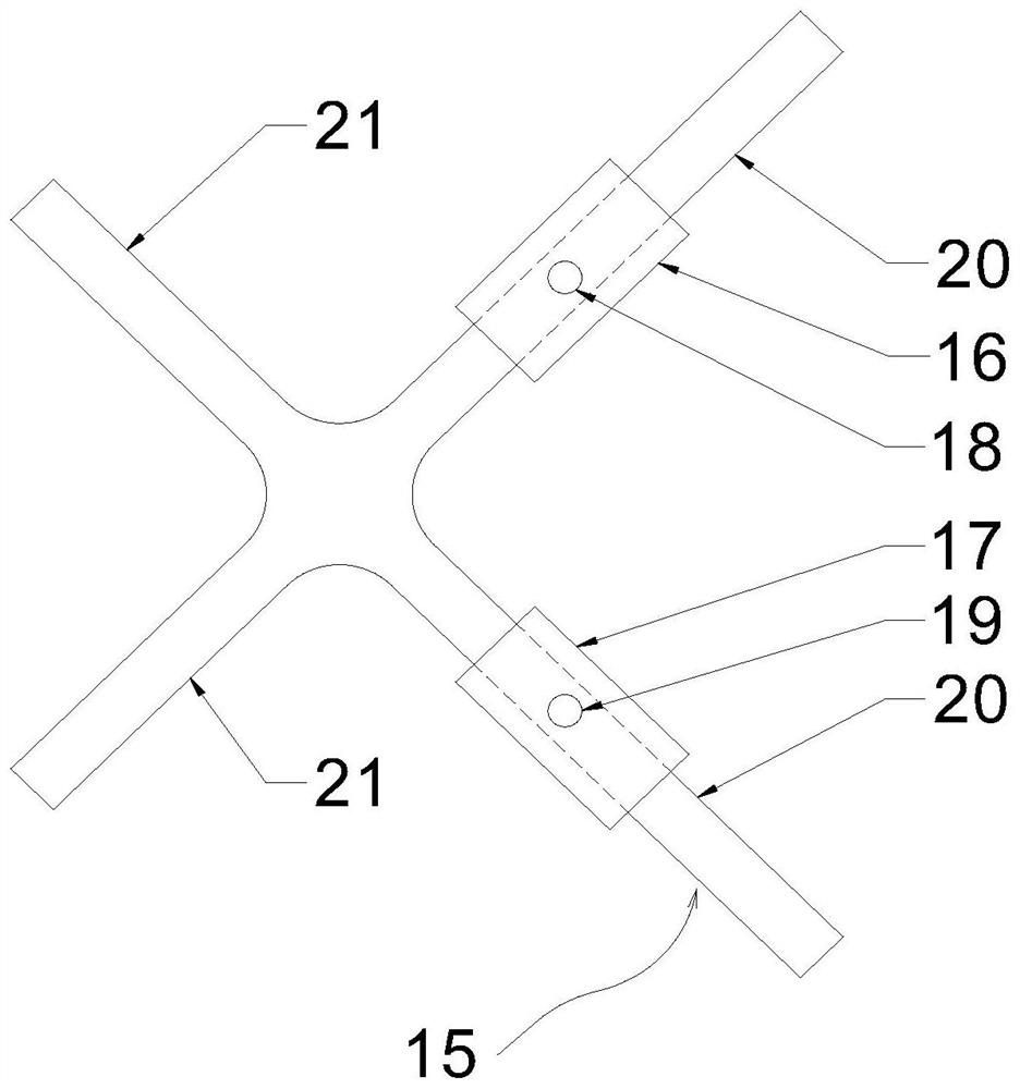
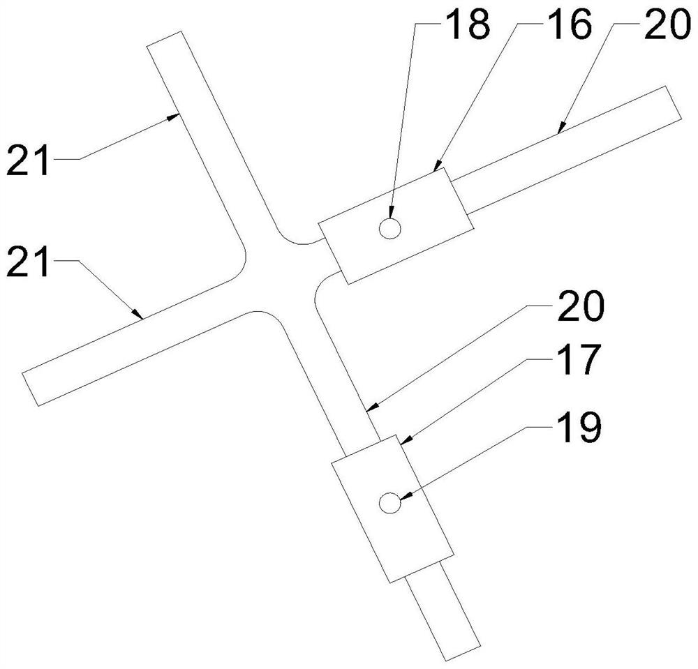
[0031] Such as Figure 1 to Figure 4 As shown, an SCR low-temperature denitrification device includes a reactor shell 1 , an ammonia injection grid 2 , a catalyst storage cylinder 3 , a turning member 4 and a reactor inner tube 5 . The top of the reactor shell 1 has a flue gas inlet 6 and the bottom has a flue gas outlet 7, and the desulfurized low-temperature flue gas (170-250° C.) is injected into the reactor shell 1 through the flue gas inlet 6 for denitrification.

[0032] A spray head 8 connected to the ammonia spray pipeline is installed on the ammonia spray grid 2. The spray head 8 sprays gasified ammonia gas to denitrify the flue gas containing NOX. The main products after the reaction are N2 and H2O. After the ammonium salt, dust and other pollutants are removed from the storage cylinder, the flue gas is discharged from the reactor shell 1 through the flue gas outlet 7 .

[0033] The catalyst storage cylinder 3 is fixed in the reactor shell 1 and is located below the...

Embodiment 2

[0049] Such as Figure 5 As shown, the difference between this embodiment and Embodiment 1 is that the base structure is different. The base of this embodiment includes a plurality of arc-shaped deflectors 32, and the deflectors 32 are arranged along a spiral trajectory, and the spiral trajectory is opposite to each other. There is an air intake gap 33 between the adjacent deflectors 32, and the airflow flowing out from the smoke overflow channel 10 passes through the air intake gap 33 and then quickly flows into the smoke outlet 7 along a spiral trajectory, and then is sucked into the chimney by the induced draft fan. Among them, several vent holes 29 are also provided on the outermost circle of deflector plates, so that the airflow in the smoke overflow channel 10 can quickly enter the spiral trajectory of the inner circle through the vent holes 29 .


PUM


Abstract

The invention provides an SCR low-temperature denitrification device, which includes a reactor shell, which has a flue gas inlet and a flue gas outlet; an ammonia spray grid, which is equipped with a spray head; a catalyst storage cylinder and the inner wall of the reactor shell A flue gas overflow channel is left, and the flue gas overflow channel is connected to the flue gas outlet; the catalyst storage cylinder includes a catalyst outer cylinder and a catalyst inner cylinder located in the catalyst outer cylinder, and a turning member is installed in the catalyst inner cylinder, and the turning member has a fork that can reciprocate and rotate When the fork-shaped piece rotates, the catalyst particles in the catalyst inner cylinder are stirred; the reactor inner tube is located in the middle of the catalyst outer cylinder, the catalyst inner cylinder is close to the reactor inner tube, and the top of the reactor inner tube is provided with an air inlet. The bottom of the inner tube of the reactor is a sealed structure, and the flue gas entering the inner tube of the reactor from the air inlet radially passes through the catalyst inner cylinder and the catalyst outer cylinder and then enters the flue gas overflow channel. The invention can solve the problems that the catalyst is easy to agglomerate and deactivate and the catalytic efficiency is low in the denitrification reactor.

Description

technical field [0001] The invention belongs to the technical field of environmental protection equipment, and in particular relates to an SCR low-temperature denitrification device. Background technique [0002] The pollutants in the lime kiln flue gas mainly include dust, sulfur dioxide, nitrogen oxides, etc. The flue gas treatment path can first desulfurize it, then enter the high-temperature bag dust removal, and then enter the SCR reactor for denitrification, and finally discharge it into the air through the induced draft fan. in the chimney. [0003] Since the desulfurized flue gas still contains a small amount of SOX, it reacts with the ammonia in the SCR reactor to form ammonium salts, and the ammonium salts are absorbed in the catalyst of the reactor, which is likely to cause the catalyst to agglomerate or deactivate due to the increase in viscosity. The operating period of the catalyst is shortened. In addition, since the catalyst bed is usually a fixed bed, unde...

Claims


Application Information

Patent Timeline
Patent Type & Authority Patents(China)
IPC IPC(8): B01D53/90B01D53/88B01D53/56
CPCB01D53/90B01D53/8631B01D53/88
Inventor 范兰张锐万加兵王苏林
Owner YANCHENG LANFENG ENVIRONMENTAL ENG TECH
Learn More