Feeding mechanism of heat exchanger bending machine and bending machine applying feeding mechanism

A technology of heat exchangers and feeding mechanisms, applied in heat exchange equipment, feeding devices, positioning devices, etc., can solve the problem of stuck workpieces to be bent, low operability of bending machines, and increased space occupied by bending machines And other issues

Pending Publication Date: 2021-03-26
OMS MASCH CO LTD
View PDF1 Cites 0 Cited by
  • Summary
  • Abstract
  • Description
  • Claims
  • Application Information

AI Technical Summary

Problems solved by technology

[0004] In the traditional tube bundle bending forming process, most of the heat exchangers to be bent are manually transported to the bending die in the main machine of the bending machine through the input end of the main machine of the bending machine, and then bent and formed. The work efficiency of the method is low and the labor intensity is high
[0005] In order to solve the above problems, the applicant has created a related feeding mechanism before. For details, please refer to the announcement number CN 104690182 B. The patent name is an invention patent for a feeding component of a bending machine. The technical solution is disclosed The feeding component of the bending machine carries the workpiece to be bent (such as a heat exchanger to be bent) on the loading platform and is pushed by the material shifting mechanism to realize automatic transportation, which can reduce labor intensity and improve work efficiency. Efficiency; and the feeding platform is driven up or down by the feeding lifting mechanism to adjust the height of the feeding platform, so that the feeding platform can be accurately docked with the main machine of the external bending machine, so that the feeding component is connected to the main machine of the external bending machine The entire process of conveying the workpiece to be bent and receiving the material from the main machine of the external bending machine is carried out stably and smoothly, which solves the problem that the loading platform cannot be accurately docked with the main machine of the external bending machine due to the existence of various errors such as assembly errors ; In addition, the material loading platform can still normally push the workpieces to be bent under different height positions by using the independent material shifting mechanism and feeding and conveying components, but this structure uses the pushing method to push the workpieces to be bent Entering into the main machine of the bending machine, during the pushing process of the workpiece to b

Method used


Image

  • Feeding mechanism of heat exchanger bending machine and bending machine applying feeding mechanism
  • Feeding mechanism of heat exchanger bending machine and bending machine applying feeding mechanism
  • Feeding mechanism of heat exchanger bending machine and bending machine applying feeding mechanism

Examples


Embodiment 1

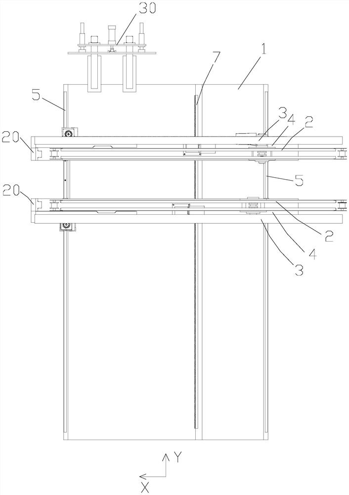
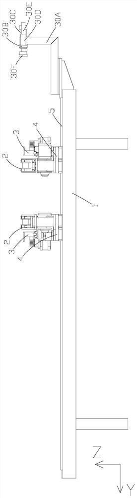
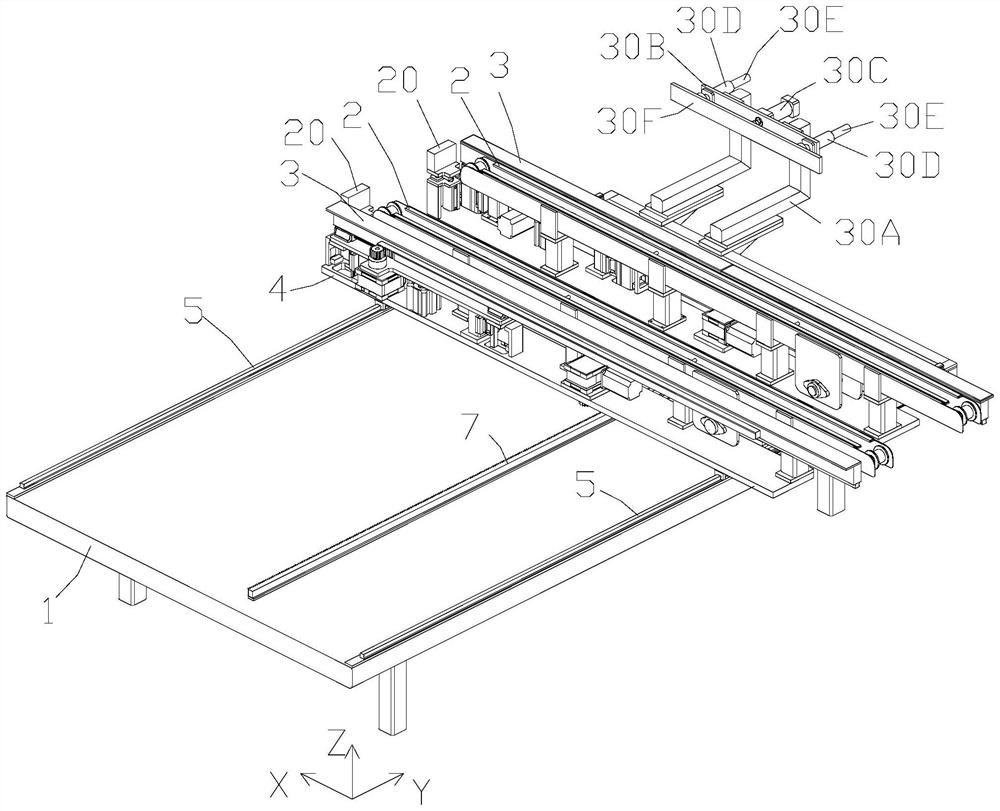
[0046] Such as Figure 1 to 8 As shown, the present embodiment provides a feeding mechanism of a heat exchanger bending machine, including an upper frame 1, and a conveying unit 10 for conveying a workpiece is provided, and the conveying unit 10 includes conveying. As part 2, the transport assembly 3 and the bottom plate 4, the conveying assembly 2 is used to carry and transport the workpiece; the transport assembly 3 is located on one side of the conveying assembly 2, and the transport assembly 3 can be along the X-axis and Z-axis direction of the upper housing 1. Move, the workpiece used to be folded on the transport assembly 2 and the workpiece is transported to the bending station or take out the workpiece of the bend on the bending station and transported to the delivery assembly 2; the bottom plate 4 The conveying path of the transport assembly 2 and the conveying path of the conveying assembly 2 and the transport assembly 2 are disposed parallel to each other along the conve...

Embodiment 2

[0056] The solution provided by the first example is applicable to the case where the distance between the workpiece transition interface and the bending station is not large, and the general improvement of the transport assembly 3 is improved, and the embodiment has made further improvements. Figure 9 with Figure 10 As shown in the present embodiment, the upper body includes an upper frame 1, which is provided in a carrier frame 8 on the upper frame 1 and a conveying unit 10 mounted on the carrier frame 8. A sheet lifting assembly 9 is provided between the object frame 8 and the upper frame 1, and the upper lifting assembly 9 drives the carrier frame 8 in the Z-axis direction of the upper housing frame 1, thereby driving the conveying unit 10. The rise or decrease, the conveying unit 10 is conveyed to the workpiece, wherein the conveying unit 10 in the present embodiment is consistent with the structure of the embodiment, which is no longer repeated, the carrier frame 8 is abov...

Embodiment 3

[0062] Such as Figure 11 with Figure 12 As shown, the present embodiment provides a bending machine, including the frame 100, a first bending mechanism 200, a second bending mechanism 300, and a second bending mechanism 300, and a second bending mechanism 300, which are provided on both sides of the workpiece can be completed on the frame 100. The follow-up mechanism 400 that can carry the workpiece on the rack 100, and the flow mechanism 400 is located between the first bending mechanism 200 and the second bending mechanism 300, further comprising the above-mentioned amounts of the first embodiment or the second embodiment. Institution 500, the upper body 500 is located on the frame 100, and the upper mechanism 500 delivers the workpiece to be bent to the bending station or takes the bending machine from the bending station. The feed mechanism, wherein the bending station is the position of the follow-up mechanism 400 of the bending machine, in the present embodiment, the follo...


PUM


Abstract

The invention discloses a feeding mechanism of a heat exchanger bending machine and the bending machine applying the feeding mechanism. The feeding mechanism comprises a feeding rack, wherein a conveying unit is arranged on the feeding rack, and comprises a conveying assembly and a carrying assembly; the conveying assembly is used for bearing and conveying workpieces; the carrying assembly is located on one side of the conveying assembly and used for bearing a workpiece to be bent on the conveying assembly and carrying the workpiece to a bending station or taking out the bent workpiece from the bending station and carrying the bent workpiece onto the conveying assembly; and the feeding mechanism can achieve feeding conveying of the workpiece to be bent and taking-out conveying of the bentworkpiece, so that the workpiece can be carried without other carrying devices after being bent, the whole mechanism of the bending machine is more compact, the occupied space of the bending machine is reduced, the feeding mode is simple and convenient, friction force borne by the workpiece in the conveying process is reduced, surface scratches are reduced, the bent workpiece is ensured to be evenly stressed in the conveying process, and the yield is increased.

Description

Technical field [0001] The present invention belongs to the field of heat exchanger bending machine, and more particularly to a feeding mechanism of a heat exchanger bending machine and a bending machine to which it is applied. Background technique [0002] Tielding heat exchanger serves a wide range of applications in the refrigeration industry as a compact heat exchanger. The forming process of the heat exchanger mainly has the following three forming processes: tube bending forming (forming a U-tube), mechanical transflation tube forming (realizing tube-mold connection), tube bundle bending formation (formation of a G-type heat exchanger ). The tube bundle is one of the key processes of the heat exchanger forming, which has an important impact on the performance of the heat exchanger. [0003] When the tube bundle is formed, the heat exchanger is first delivered to a predetermined position, so that the portion you want to be curved is close to the bending mode (roller) having ...

Claims


Application Information

Patent Timeline
IPC IPC(8): B21D7/00B21D43/02B21D43/04B21D43/12B21D45/02B21D53/08
CPCB21D7/00B21D43/026B21D43/027B21D43/04B21D43/12B21D45/02B21D53/085
Inventor 龙晓明洪伟东
Owner OMS MASCH CO LTD
Why Eureka
Try Eureka