
Flow-stabilizing slag-stopping nodular cast iron pouring structure and working method thereof

A technology of slag blocking and steady flow, which is applied in the direction of casting molds, casting mold components, manufacturing tools, etc., can solve the problems of poor products, affecting the quality of castings, and prone to defective products, so as to avoid waste, improve quality, and improve finished products rate effect

Pending Publication Date: 2021-03-26
苏州石川制铁有限公司
View PDF0 Cites 0 Cited by
  • Summary
  • Abstract
  • Description
  • Claims
  • Application Information

AI Technical Summary

Problems solved by technology

[0004] 1. Due to the slag inclusions in the molten iron, the slag inclusions may enter the sand mold during the pouring process, resulting in defects in the formed product and resulting in defective products
[0005] 2. The molten iron poured into the sprue cup is quickly dispersed to the runners, vertical runners, ingates, and sand molds of parts. The molten iron is very dispersed. Therefore, at the initial stage of pouring, it is easy to cause the temperature of the local molten iron to drop rapidly, thus affecting the quality of the casting. Quality, even if the pouring time is very strict, defective products are prone to appear

Method used


Image

  • Flow-stabilizing slag-stopping nodular cast iron pouring structure and working method thereof
  • Flow-stabilizing slag-stopping nodular cast iron pouring structure and working method thereof
  • Flow-stabilizing slag-stopping nodular cast iron pouring structure and working method thereof

Examples


Embodiment 1

[0029] The following will clearly and completely describe the technical solutions in the embodiments of the present invention with reference to the accompanying drawings in the embodiments of the present invention. Obviously, the described embodiments are only some, not all, embodiments of the present invention.

[0030] It should be noted that, in the description of the present invention, unless otherwise specified, the meaning of "plurality" is two or more; the terms "upper", "lower", "left", "right", "inner ", "outside", "front end", "rear end", "head", "tail", etc. indicate the orientation or positional relationship based on the orientation or positional relationship shown in the drawings, and are only for the convenience of describing the present invention and Simplified descriptions, rather than indicating or implying that the device or element referred to must have a particular orientation, be constructed and operate in a particular orientation, and thus should not be co...


PUM


Abstract

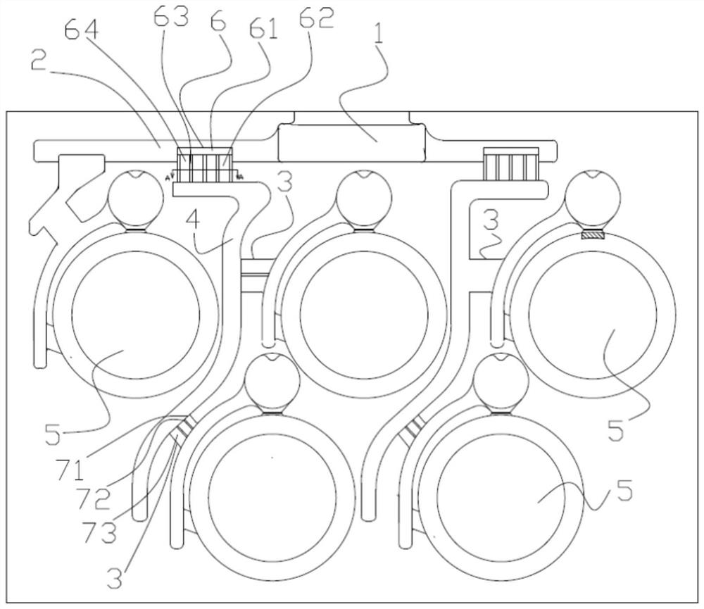
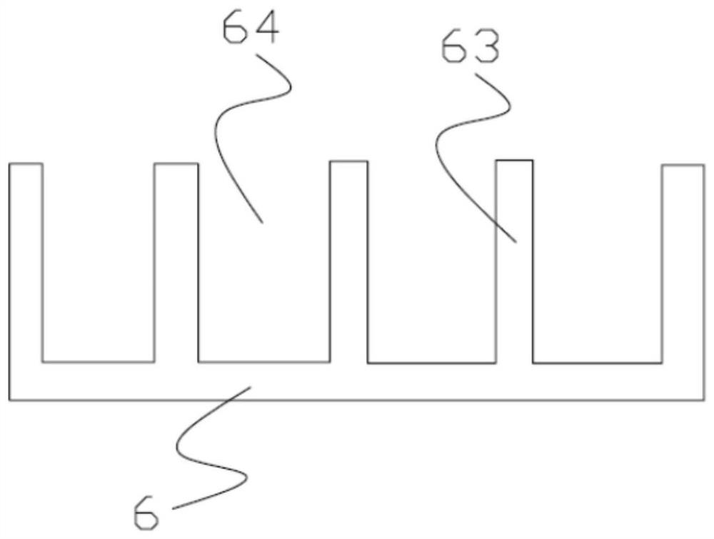
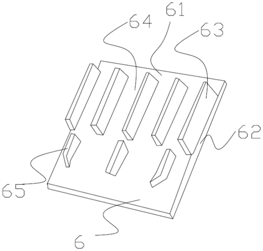
The invention discloses a flow-stabilizing slag-stopping nodular cast iron pouring structure and a working method thereof. A first flow blocking piece is arranged at the joint of a main transverse pouring gate and a longitudinal pouring gate of the flow-stabilizing slag-stopping nodular cast iron pouring structure and comprises a head part and a neck part; the head part is in a U shape with an opening formed in one side; the top end of the head part is higher than the bottom of the main transverse pouring gate; the neck part extends to the longitudinal pouring gate from the head part; and first partition pieces are arranged on the head part and the neck part at intervals and divide the U-shaped opening into a plurality of first small feeding openings. Accordingly, floating slag can be effectively prevented from flowing in, the dispersion time of molten metal can be prolonged, and the yield of products is increased.

Description

technical field [0001] The invention relates to the technical field of casting processing and manufacturing, in particular to a steady-flow slag-retaining nodular cast iron pouring structure and a working method thereof. Background technique [0002] The gating system is the channel through which molten iron flows into the cavity in the mold, and usually consists of sprue cups, runners, vertical sprues, ingates, and sand molds for parts. , and then into the part sand mold. After cooling, a casting is formed. [0003] However, the existing pouring methods often have the following two problems: [0004] 1. Due to the slag inclusions in the molten iron, the slag inclusions may enter the sand mold during the pouring process, resulting in defects in the formed products and resulting in defective products. [0005] 2. The molten iron poured into the sprue cup is quickly dispersed to the runners, vertical runners, ingates, and sand molds of parts. The molten iron is very dispers...

Claims


Application Information

Patent Timeline
IPC IPC(8): B22C9/08B22C9/02
CPCB22C9/02B22C9/082
Inventor 王莹麟施伟群伊绵森
Owner 苏州石川制铁有限公司
Learn More