Manufacturing method for reducing optical fiber loss

A manufacturing method and optical fiber loss technology, applied in the direction of manufacturing tools, glass manufacturing equipment, etc., can solve problems such as imperfect optical fiber structure, molecular bond breakage in the optical fiber structure, scattering loss, etc., so as to improve the order of molecular arrangement and increase the longitudinal The length of the hot zone and the effect of reducing the drawing tension

Inactive Publication Date: 2021-03-26
NANJING WASIN FUJIKURA OPTICAL COMM LTD
View PDF10 Cites 0 Cited by
  • Summary
  • Abstract
  • Description
  • Claims
  • Application Information

AI Technical Summary

Problems solved by technology

Imperfect fiber structure will also cause scattering loss, mainly because the crystal structure inside the fiber will affect the loss of the fiber
[0005] like figure 2 As shown, in the optical fiber preparation process, as the outer diameter of the optical rod becomes larger and the drawing speed is higher and higher, the optical rod is required to shrink from the outer diameter of the optical rod to the outer diameter of the optical fiber in a shorter time, which is limited by heating Furnace structure and process conditions, plus the standard of the outer diameter of the optical fiber has not changed, the length of the longitudinal hot zone of the optical rod has not increased compared with the past, but has been relatively shortened, which requires increasing the temperature of the heating furnace during the wire drawing process and applying more Large drawing tension to achieve smooth drawing, which makes the process of changing from the outer diameter of the optical rod to the outer diameter of the optical fiber during the drawing process changes sharply. The greater drawing tension causes greater stress in the formed optical fiber, due to Due to the fatigue effect, the optical fiber is more likely to break, and at the same time, the large drawing tension will cause the molecular bonds in the optical fiber structure to break, and the evil molecules in the optical fiber are relatively disordered, resulting in a large loss of the optical fiber

Method used


Image

  • Manufacturing method for reducing optical fiber loss
  • Manufacturing method for reducing optical fiber loss
  • Manufacturing method for reducing optical fiber loss

Examples


Embodiment 1

[0037] Longitudinal Hot Zone Length Screening Example

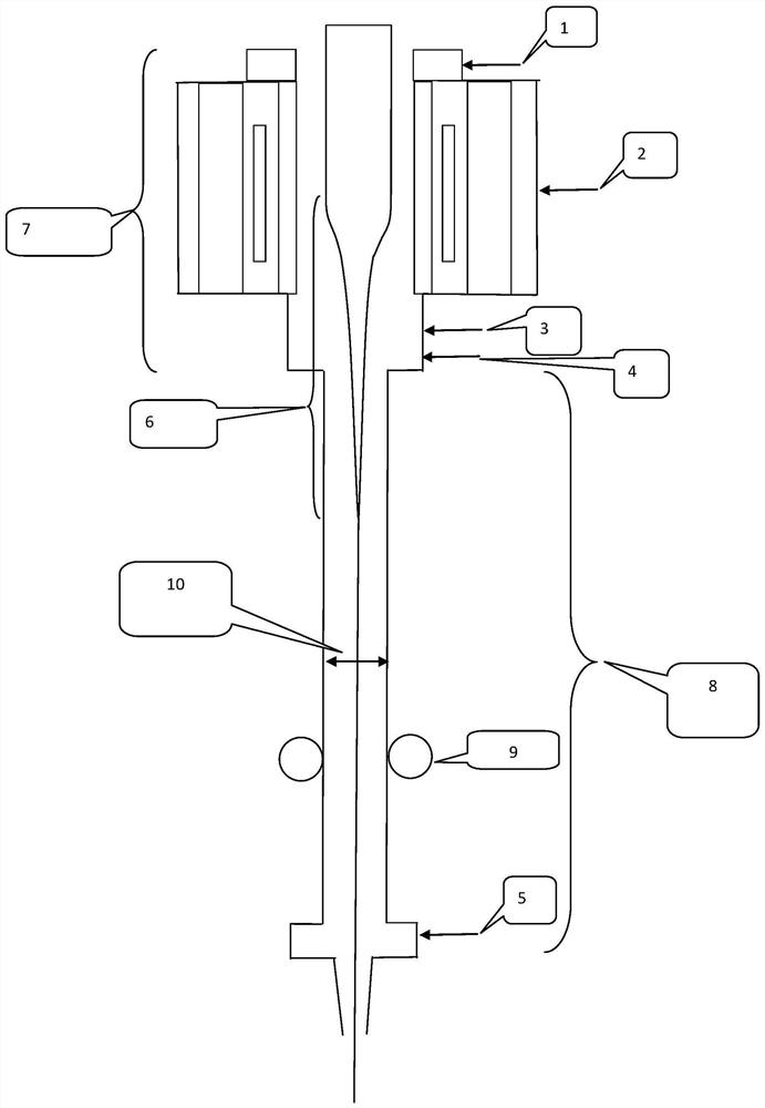
[0038] Such as image 3 As shown, the length of the hot zone of the existing heating furnace is generally 900-1000mm. The height of the original hot zone 7 of the heating furnace adopted by the applicant of the present invention is 960mm, and the loss of the output optical fiber is relatively high. The length setting gradient changes are 2000mm, 2100mm, 2200mm, ..., 4000mm, and the performance test is carried out on the final produced optical fiber. The results are shown in Figure 4 and Figure 5 shown.

[0039] From Figure 4 and Figure 5 It can be seen that the length of the increased longitudinal hot zone needs to exceed 2500mm, that is, the total length of the hot zone must be more than 3460mm to produce a positive improvement in the loss of the optical fiber. Theoretically, the longer the length of the vertical hot zone, the better the loss of the optical fiber. It is found in the test that when the length of ...

Embodiment 2

[0043] Such as image 3 As shown, the inert gas inlet 1 / 2 / 3 / 4 / 5 in the figure, a total of 5 positions are used to feed inert gas. After a long period of exploration, it is determined that the distance between the inlet hole and the highest point of the heating area is 50 ~70mm, 660~680mm, 875~895mm, 932~952mm, 4450~4470mm, the performance of the output optical fiber is the most stable; the flow rate of the inert gas is 3L / min~5L / min, 3L / min~4L respectively / min, 3L / min~5L / min, 5L / min~11L / min, 6L / min~9L / min. The average gas flow combinations are 4L / min, 3.5L / min, 4L / min, 8L / min, 7.5L / min.

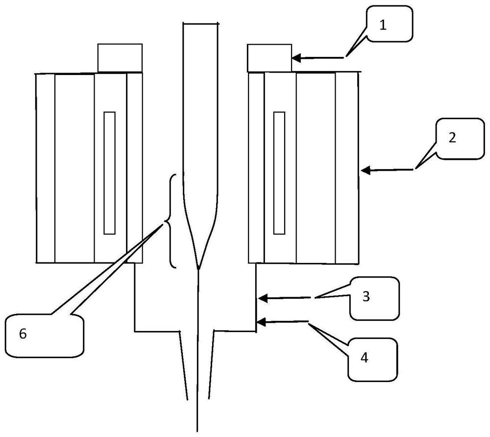
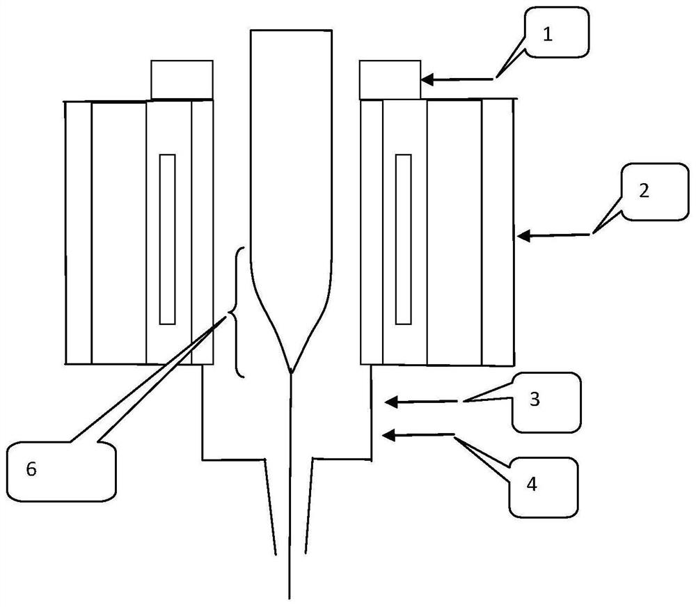
[0044] With the original heating furnace (such as figure 2 (shown) compared to: only the inert gas inlet 1 / 2 / 3 / 4 in the original heat zone 7, a total of 4 positions are fed with inert gas, and the flow rate of the feed is 5L / min~6L / min, 1.5L / min respectively ~2.5L / min, 2.5L / min~3.5L / min, 12L / min~14L / min, the average gas flow combination is 6L / min, 2L / min, 3L / min, 13L / min; The performance...

Embodiment 3

[0049] Such as image 3 It is shown that after the length of the longitudinal hot zone is determined, the gradient changes of the inner diameter 10 of the vertical growth hot zone are 30mm, 40mm, ..., 100mm respectively. After verification, the inner diameter of 40mm to 60mm meets the production requirements, and the inner diameter is too small. It is easy to be scrapped due to poor strength, and when the inner diameter is too large, more gas needs to be introduced. Considering the economy, the final inner diameter of the hot zone is determined to be 50mm.


PUM

PropertyMeasurementUnit
lengthaaaaaaaaaa
lengthaaaaaaaaaa

Abstract

The invention discloses a manufacturing method for reducing optical fiber loss. An optical wand drawing process is adopted for optical fiber manufacturing. According to the manufacturing method, the length of a longitudinal hot area in the optical wand drawing process is increased, and inert gas is introduced into a lengthened area to form stable gas flow. By increasing the longitudinal heating height (namely the length of the longitudinal hot area of a heating furnace) of an optical wand, the process of reducing the diameter of the optical wand becomes gentle; the smooth outer diameter transition enables the molecular arrangement to be more orderly in the process of continuously reducing the diameter of the optical wand into the diameter of a bare fiber, can effectively reduce the drawingtension applied to the optical fiber by the optical fiber drawing, further improves the molecular arrangement orderliness in the optical fiber drawing process, and further reduces the optical fiber loss.

Description

technical field [0001] The invention relates to a manufacturing method of optical fiber products, in particular to a manufacturing method for reducing optical fiber loss. Background technique [0002] The loss of optical fiber is the main performance of optical fiber transmission. The loss is large and the transmission distance is short. For long-distance transmission and cost considerations, the loss requirement of optical fiber is getting higher and higher. The loss of optical fiber is divided into intrinsic loss and manufacturing loss. [0003] Intrinsic loss refers to a kind of loss inherent in the fiber material, which is unavoidable, and it determines the loss limit of Rayleigh scattering of the fiber. The intrinsic loss of the silica fiber includes the loss caused by the intrinsic absorption and Rayleigh scattering of the fiber. [0004] Optical fiber manufacturing loss is generated during the process of manufacturing optical fiber, mainly caused by the absorption of...

Claims


Application Information

Patent Timeline
Patent Type & Authority Applications(China)
IPC IPC(8): C03B37/027
CPCC03B37/02718C03B37/027
Inventor 周利佳邹根谢晓红席春磊
Owner NANJING WASIN FUJIKURA OPTICAL COMM LTD
Why Eureka
Try Eureka