Eureka AIR delivers breakthrough ideas for toughest innovation challenges, trusted by R&D personnel around the world.

Circuit test wire clamp

A technology of circuit testing and wire clips, which is applied to the components of electrical measuring instruments, measuring devices, and measuring electrical variables, etc. It can solve the problems of difficult manufacturing of test wire clips and poor contact effects

Pending Publication Date: 2021-03-30
BAICHENG POWER SUPPLY CO OF STATE GRID JILIN ELECTRIC POWER CO LTD
View PDF0 Cites 1 Cited by
  • Summary
  • Abstract
  • Description
  • Claims
  • Application Information

AI Technical Summary

Problems solved by technology

[0005] In view of this, the object of the present invention is to provide a circuit test clamp, which can effectively solve the problems of difficult manufacture and poor contact effect of the test clamp of the handcart-type high-voltage switch circuit resistance tester

Method used


Image

  • Circuit test wire clamp

Examples


Embodiment Construction

[0022] The embodiment of the invention discloses a circuit test wire clamp, which can effectively solve the problems of difficult manufacture and poor contact effect of the test wire clamp of a handcart-type high-voltage switch circuit resistance tester.

[0023] The following will clearly and completely describe the technical solutions in the embodiments of the present invention with reference to the accompanying drawings in the embodiments of the present invention. Obviously, the described embodiments are only some, not all, embodiments of the present invention. Based on the embodiments of the present invention, all other embodiments obtained by persons of ordinary skill in the art without making creative efforts belong to the protection scope of the present invention.

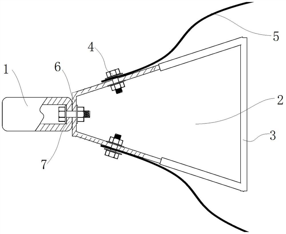
[0024] see figure 1 , figure 1 A schematic structural diagram of a circuit test wire clip provided by an embodiment of the present invention.

[0025] In a specific embodiment, this embodiment provides a c...


PUM


Abstract

The invention discloses a circuit test wire clamp, which comprises a connecting plug and an annular operation part bent by a metal rod body, and is characterized in that the middle part of the front side edge of the operation part is connected with the connecting plug and is in conductive contact with the connecting plug, the rear side edge of the operation part is provided with an insulation partfor holding, and at least one side edge of the left and right sides of the operation part is provided with a conductive connection hole. In the manufacturing process, only the connecting plug matchedwith the connecting terminal, the technical rod body and the like need to be selected, then the technical rod body is annularly bent, two conductive connecting holes are drilled in the technical rodbody, then the technical rod body is connected with the connecting plug, and the whole manufacturing process is simple and convenient. Moreover, because the connecting plug is connected with the corresponding test equipment in an inserted manner, a better contact effect can be ensured, the problem of infirm contact is avoided, and the test accuracy is ensured. In conclusion, the circuit test wireclamp can effectively solve the problem that an existing circuit test wire clamp is inconvenient to manufacture and poor in contact effect.

Description

technical field [0001] The invention relates to the technical field of circuit connection equipment, and more specifically, to a circuit test wire clip. Background technique [0002] At present, various power equipment failures occur frequently. Actively discovering failures through tests will avoid switchgear failures, which can greatly improve the stability and safety of power system operation. [0003] At present, the test line clamp of the handcart type high-voltage switch circuit resistance tester is to connect the test line and the contact of the equipment under test in the form of a clip. During the many tests, there were the following problems: During the circuit resistance test of the handcart-type high-voltage switch, due to the mismatch between the equipment clamp and the switch under test, the contact resistance was large, and the moving contact between the equipment clamp and the handcart-type high-voltage switch The actual test results have a high degree of di...

Claims


Application Information

Patent Timeline
Patent Type & Authority Applications(China)
IPC IPC(8): G01R1/04
CPCG01R1/0425
Inventor 潘中峰于江刘琳梁祥伟车文成郑玉山梁晓龙张辎猛王辉许文龙杜祥张轶博王壮张志良
Owner BAICHENG POWER SUPPLY CO OF STATE GRID JILIN ELECTRIC POWER CO LTD
Why Eureka
Eureka Blog
Learn More