Composite material processing machine tool

A technology for processing machine tools and composite materials, applied in metal processing equipment, manufacturing tools, welding equipment and other directions, can solve the problems of cumbersome operation mode, poor equipment functionality, single processing method, etc., to improve functional diversity, improve work efficiency, The effect of improving machining accuracy

Active Publication Date: 2021-04-02
山东中航泰达复合材料有限公司
7 Cites 0 Cited by

AI-Extracted Technical Summary

Problems solved by technology

[0002] As we all know, a composite material usually refers to a material with new properties composed of two or more materials with different properties through chemical or physical methods, which can meet various needs. Composite materials can be metal or non-metal And other materials are processed and produced. When composite materials are processed, it is usually necessary to cut the plate-shaped composite material according to the actual specification requirements. ...

Abstract

The invention relates to the technical field of mechanical equipment, in particular to a composite material processing machine tool, which can conveniently perform multi-angle and multi-arc processingtreatment on a material by automatically cutting the composite material, so that the degree of freedom of the equipment for material processing is improved, the processing treatment on the material according to specified requirements is facilitated, and the functional diversity of the equipment is improved; and meanwhile, the equipment can conduct one-time forming processing on the composite material, so that the processing speed is effectively increased, the working efficiency is improved, and the practicability and the reliability are improved. The composite material processing machine toolcomprises a workbench, four sets of supporting legs, a mounting plate and a laser generator, wherein the four sets of supporting legs are evenly mounted at the bottom of the workbench; clamping mechanisms are arranged on the front side and the rear side of the workbench; an adjusting mechanism is arranged on the top of the workbench; an S-shaped mechanism is arranged on the adjusting mechanism; and the mounting plate is mounted at the head of the left side of the S-shaped mechanism.

Application Domain

Technology Topic

Image

  • Composite material processing machine tool
  • Composite material processing machine tool
  • Composite material processing machine tool

Examples

  • Experimental program(1)

Example Embodiment

[0021] The specific implementation manners of the present invention will be further described in detail below in conjunction with the accompanying drawings and embodiments. The following examples are used to illustrate the present invention, but are not intended to limit the scope of the present invention.
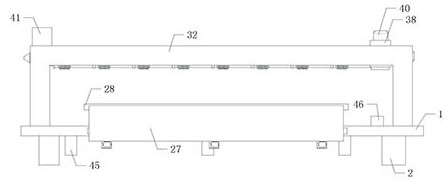
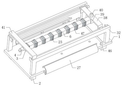
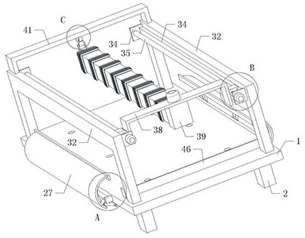
[0022] like Figure 1 to Figure 7 As shown, a composite material processing machine tool of the present invention, when it is working, places the plate-shaped composite material on the workbench 1 and fixes it through two sets of clamping mechanisms. The serpentine mechanism can drive the mounting plate 3 and the laser generator The device 4 moves at any position on the composite material, and the laser generator 4 is turned on, and the laser generator 4 can perform laser cutting processing on the composite material, thereby realizing automatic cutting processing of the material.
[0023] The main functions realized by the present invention are: through automatic cutting of the composite material, it is convenient to process the material with multi-angle and multi-arc, improve the freedom of equipment for material processing, and facilitate the processing of the material according to the specified requirements , improve the diversity of equipment functions, and at the same time, the equipment can perform one-time molding processing on composite materials, effectively increasing the processing speed and improving work efficiency; the working mode of the serpentine mechanism is to open the first motor 17, and the first motor 17 drives the first gear 18 Rotate, the first gear 18 meshes with the arc-shaped row of teeth 14, the first gear 18 drives the arc-shaped row of teeth 14 to rotate, the arc-shaped row of teeth 14 slides on the sliding seat 15, and the arc-shaped row of teeth 14 drives the right side through the turntable 13 The side square adjustment plate 7 tilts, and the right square adjustment plate 7 pulls the left square adjustment plate 7 to tilt through four sets of pull rods 12. The left square adjustment plate 7 drives the steering sleeve 5 to tilt, thereby changing the direction of the steering sleeve 5, and the right side square adjustment plate 7 The adjustment plate 7 is tilted, and the square adjustment plate 7 on the right side drives the support column 8 to rotate on the support ball 9, and the cross support frame 11, the support shaft 10 and the support ball 9 support the support column 8 and the square adjustment plate 7 on the right side. The second motor 22, the second motor 22 drives the second gear 21 to rotate, the second gear 21 is meshed with the external gear ring 19, the second gear 21 drives the external gear ring 19 to rotate, and the external gear ring 19 drives the arc through the slide seat 15 The tooth row 14 rotates along the axis direction of the outer gear ring 19, and the arc-shaped tooth row 14 drives the turntable 13 to rotate on the right side square adjustment plate 7, thereby adjusting the sliding direction of the arc-shaped tooth row 14 on the sliding seat 15, which is convenient for right The inclination direction of the side square adjustment plate 7 is adjusted to facilitate the adjustment of the inclination direction of the steering sleeve 5. The four sets of second fixed plates 20 support the outer gear ring 19. The steering sleeve 5 and the adjustment sleeve in the adjacent two groups of steering mechanisms 6. Carry out the end-to-end connection through the connecting ring 47, and control the inclination direction of the steering sleeve 5 in each group of writing mechanisms, thereby controlling the overall bending shape and direction of the serpentine mechanism, making it convenient for the left end head of the serpentine mechanism, the mounting plate 3 and the laser The position of the generator 4 is adjusted, thereby controlling the laser generator 4 to maintain a vertical state and move on the composite material according to actual needs, so as to realize the laser cutting work of the composite material by the laser generator 4, and facilitate automatic cutting of the composite material; When the steering sleeve 5 is tilted, the steering sleeve 5 drives the folding shield 23 to bend synchronously. By setting the folding shield 23, it is convenient to block the space between the steering sleeve 5 and the adjustment sleeve 6, so as to facilitate the shielding and protection of the equipment inside. The working mode of the clamping mechanism is to push the arc extruding plate 27 to rotate through three groups of first hydraulic cylinders 30, and the arc extruding plate 27 drives three groups of connecting frames 26 and rotating shafts 24 on two groups of third fixing plates 25 Rotate, at the same time the arc-shaped extrusion plate 27 drives the anti-skid plate 28 to rotate, the anti-skid plate 28 is in contact with the top of the composite material on the top of the workbench 1 and is extruded and fixed, thereby fixing the plate-shaped composite material on the workbench 1, Three sets of reinforcing plates 29 can support the arc extruded plate 27, thereby strengthening the intensity of the arc extruded plate 27 and avoiding its bending deformation; The working mode of the whole mechanism is to control and open two groups of third motors 36, and the two groups of third motors 36 respectively drive two groups of leading screws 35 to rotate, and the two groups of leading screws 35 synchronously push two groups of moving blocks 37 to move left and right, and the two groups of moving blocks The block 37 drives the second bow frame 38, the rotating seat 39, the fourth motor 40 and the right end tail of the serpentine mechanism to move left and right, so as to facilitate the adjustment of the tail position of the serpentine mechanism and facilitate the movement of the left end head of the serpentine mechanism. The position is adjusted, and the fourth motor 40 is controlled to be turned on. The fourth motor 40 drives the right end tail of the serpentine mechanism to rotate through the rotating seat 39, so as to facilitate the adjustment of the serpentine mechanism, the mounting plate 3 and the laser generator 4 to move to the second bow frame 38 the right side of the serpentine mechanism, thereby adjusting the working area of ​​the serpentine mechanism; by setting the third bow frame 41, hook 42, hanging strap 43 and leaf spring 44, it is convenient to install the left end of the mounting plate 3, laser generator 4 and serpentine mechanism It is convenient to fix the serpentine mechanism, mounting plate 3 and laser generator 4 when the equipment is idle. When the equipment is working, move the hook 42 and separate the hanging belt 43 from the hook 42. The leaf spring 44 is in an elastically deformed state, and the leaf spring 44 pushes the hook 42 to rotate on the third bow frame 41 to the left side of the third bow frame 41. At this time, the hook 42 is in a retracted state; multiple sets of second hydraulic cylinders 45 are controlled to extend sideways The output ends pass through multiple groups of through holes and extend to the upper side of the workbench 1. At this time, the tops of the multiple sets of second hydraulic cylinders 45 support the bottom of the composite material, so that the composite material processed on the workbench 1 can be easily taken out. Bottom; the composite material is placed on the workbench 1, and the right end of the composite material is in contact with the inner wall of the bow-shaped positioning plate 46. By setting the bow-shaped positioning plate 46, the composite material can be easily positioned, and the processing accuracy can be improved, and the practicability and reliability can be improved. sex.
[0024] A kind of composite material processing machine tool of the present invention, its installation method, connection method or setting method are all common mechanical methods, as long as it can achieve its beneficial effect, it can be implemented; laser generator 4, folding shield 23, first hydraulic pressure The oil cylinder 30 and the second hydraulic oil cylinder 45 can be purchased in the market.
[0025] The above is only a preferred embodiment of the present invention, it should be pointed out that for those of ordinary skill in the art, without departing from the technical principle of the present invention, some improvements and modifications can also be made, these improvements and modifications It should also be regarded as the protection scope of the present invention.

PUM

no PUM

Description & Claims & Application Information

We can also present the details of the Description, Claims and Application information to help users get a comprehensive understanding of the technical details of the patent, such as background art, summary of invention, brief description of drawings, description of embodiments, and other original content. On the other hand, users can also determine the specific scope of protection of the technology through the list of claims; as well as understand the changes in the life cycle of the technology with the presentation of the patent timeline. Login to view more.

Similar technology patents

Classification and recommendation of technical efficacy words

  • Improve machining accuracy
  • Improve availability and reliability

Numerical control electrolyze mechanical compound processing machine tool

InactiveCN101249578AEliminate installation errorsImprove machining accuracyFeeding apparatusElectric circuitsElectric machineryComposite cathode
Owner:CHANGZHOU INST OF TECH
Why Eureka
Try Eureka