
Electronic radiator punching and cutting device

A cutting device and heat sink technology, applied in the direction of shearing device, positioning device, boring/drilling, etc., can solve the problems of aluminum chips splashing, and achieve the effects of avoiding measurement errors, reducing cleaning workload, and reasonable design

Inactive Publication Date: 2021-04-02
ZHENJIANG CITY CHANGHONG HEATSINK CO LTD
View PDF8 Cites 1 Cited by
  • Summary
  • Abstract
  • Description
  • Claims
  • Application Information

AI Technical Summary

Problems solved by technology

[0004] The object of the present invention is to provide a kind of electronic radiator punching and cutting device, to solve the problem that when the existing electronic radiator proposed in the above-mentioned background technology is cutting, a large amount of aluminum scraps are directly splashed on the ground and need to be cleaned by the operator. After filtering, it can be recycled and reused, and when the electronic radiator is being processed, the cutting length needs to be determined manually by observing the scale on the base. Large errors are prone to occur when viewing with the naked eye. Debris, issues requiring staff to clean it

Method used


Image

  • Electronic radiator punching and cutting device
  • Electronic radiator punching and cutting device
  • Electronic radiator punching and cutting device

Examples


Embodiment Construction

[0031] The following will clearly and completely describe the technical solutions in the embodiments of the present invention with reference to the accompanying drawings in the embodiments of the present invention. Obviously, the described embodiments are only some, not all, embodiments of the present invention. Based on the embodiments of the present invention, all other embodiments obtained by persons of ordinary skill in the art without making creative efforts belong to the protection scope of the present invention.

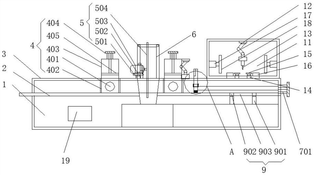
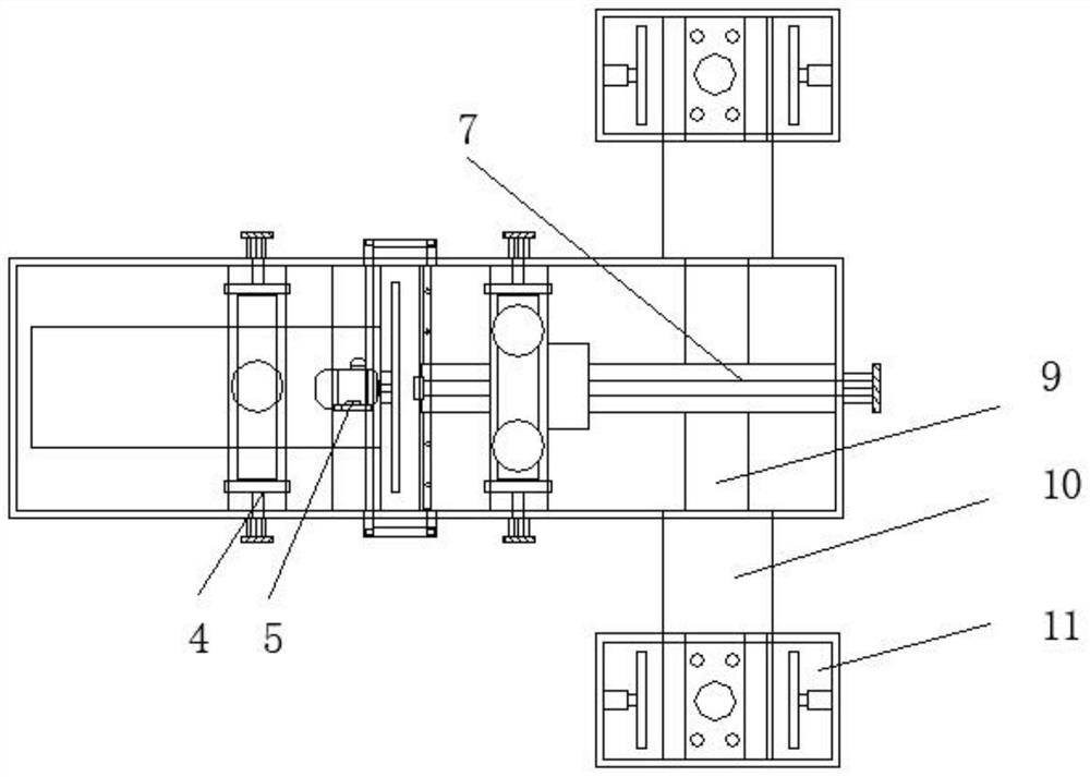
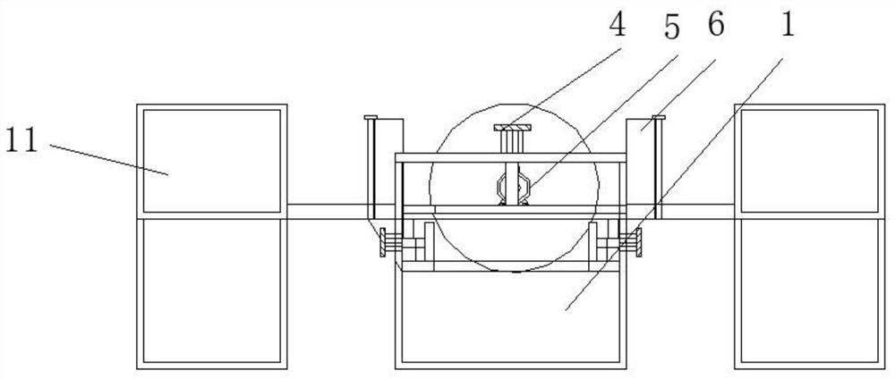
[0032] see Figure 1-7 , the present invention provides a technical solution: an electronic radiator punching and cutting device, such as figure 1 , image 3 , Figure 5 , Image 6 with Figure 7As shown, the first conveyor belt 2 is fixed on the upper left side of the base 1, and the baffle 3 is fixed on the upper side of the base 1, and the auxiliary clamping assembly 4 is fixed on the baffle 3; the auxiliary clamping assembly 4 includes a first hydrauli...


PUM


Abstract

The invention discloses an electronic radiator punching and cutting device. The electronic radiator punching and cutting device comprises a base, a cutting assembly, a moving assembly and a third conveying belt, a first conveying belt is fixed to the upper end of the left side of the base, the cutting assembly is used for cutting an electronic radiator shell, a material blocking and collecting assembly is located on the left side of a length measuring assembly, the moving assembly is used for conveying and moving the cut electronic radiator shell, the third conveying belt is fixed to the upperend of the right side of a baffle, manipulators are fixed to the upper side of the interior of a concentric-square-shaped plate and the outer wall of the right end of a right auxiliary clamping assembly, a third electric telescopic rod is fixed to the lower side of the interior of the concentric-square-shaped plate, and a fourth electric telescopic rod is fixed to the inner wall of the concentric-square-shaped plate. The electronic radiator punching and cutting device has the advantages that splashing of chippings is reduced, the cutting length of an electronic radiator can be accurately measured, chippings on an operation table can be cleaned, two sets of drilling devices can work, the structure is simple, the design is reasonable, and maintenance is easy.

Description

technical field [0001] The invention relates to the technical field of electronic radiators, in particular to an electronic radiator punching and cutting device. Background technique [0002] The main function of the electronic radiator is to absorb the heat generated by the electronic components, and then transfer and dissipate it, thereby reducing the temperature of the components and avoiding the damage of the components due to the high working temperature; the commonly used radiator material is mainly aluminum Alloy, copper alloy, and other materials; the choice of electronic radiator should be based on the working environment, working conditions, size and installation method of electronic components. [0003] When the existing electronic radiator is being cut and processed, a large amount of aluminum shavings are directly splashed on the ground, and the operator needs to clean it and filter it before it can be recycled and reused, which is time-consuming and laborious. ...

Claims


Application Information

Patent Timeline
IPC IPC(8): B23P23/02B23Q3/06B23Q3/08B23D19/00B23Q11/00B23Q41/02B23B41/00B23Q17/24
CPCB23B41/00B23D19/00B23P23/02B23Q3/062B23Q3/082B23Q11/0042B23Q11/0067B23Q17/2428B23Q41/02
Inventor 王峰
Owner ZHENJIANG CITY CHANGHONG HEATSINK CO LTD
Learn More