
Porous buried pipe heat exchanger heat transfer dimension reduction analysis method and system

A technology of buried tube heat exchanger and dimensionality reduction analysis, applied in the direction of thermal conductivity of materials, instruments, thermal development of materials, etc. The effect of improving efficiency, improving computing efficiency, and improving computing speed

Active Publication Date: 2021-04-02
山东中瑞新能源科技有限公司
View PDF5 Cites 4 Cited by
  • Summary
  • Abstract
  • Description
  • Claims
  • Application Information

AI Technical Summary

Problems solved by technology

However, the heat transfer problem of buried tube heat exchangers involves a large span of space, ranging from the thickness of the pipe wall in millimeters to the depth of kilometers, and the geometric configuration is also very complicated; at the same time, the time span involved in the problem is also very large. Large, the change of load over time and the characteristic time of flow can be in the order of minutes, and the time span of system operation is as long as more than ten years
Therefore, the numerical simulation of this kind of heat transfer problem will need to divide the domain into a huge number of cells and consume a lot of computing time
The heat transfer of a single-hole buried tube heat exchanger can be described by a two-dimensional problem in cylindrical coordinates, but when solving the heat transfer of a buried tube heat exchanger group composed of more than two boreholes, it will involve three-dimensional For unsteady heat transfer problems, the calculation workload is often unbearably large, and it is very difficult to perform basic heat transfer analysis or directly solve engineering problems
Therefore, the existing numerical analysis and research on the heat transfer of buried tube heat exchangers (especially medium-deep buried tube heat exchangers) mainly involves single-hole buried tube heat exchangers, and is not suitable for porous buried tube heat exchangers. heater scene

Method used

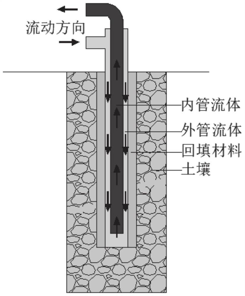
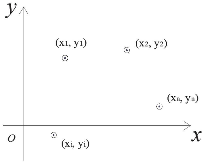
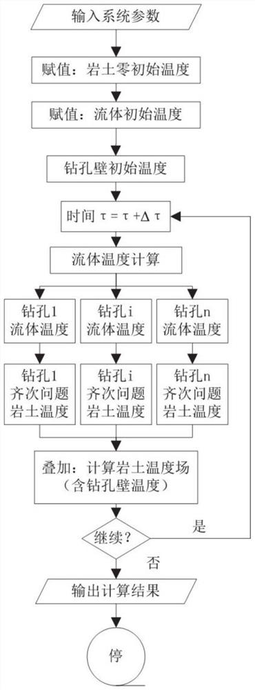

Image

  • Porous buried pipe heat exchanger heat transfer dimension reduction analysis method and system
  • Porous buried pipe heat exchanger heat transfer dimension reduction analysis method and system
  • Porous buried pipe heat exchanger heat transfer dimension reduction analysis method and system

Examples


Embodiment Construction

[0045] The present invention will be further described below in conjunction with the accompanying drawings and embodiments.

[0046] It should be noted that the following detailed description is exemplary and intended to provide further explanation of the present invention. Unless defined otherwise, all technical and scientific terms used herein have the same meaning as commonly understood by one of ordinary skill in the art to which this invention belongs.

[0047] It should be noted that the terminology used here is only for describing specific embodiments, and is not intended to limit exemplary embodiments according to the present invention. As used herein, unless the context clearly dictates otherwise, the singular is intended to include the plural, and it should also be understood that when the terms "comprising" and / or "comprising" are used in this specification, they mean There are features, steps, operations, means, components and / or combinations thereof.

[0048] In...


PUM


Abstract

According to the porous buried pipe heat exchanger heat transfer dimension reduction analysis method and system, the superposition principle is utilized to decompose the three-dimensional heat transfer problem of the porous buried pipe heat exchanger into superposition of multiple single-hole two-dimensional problems, dimension reduction numerical calculation is achieved, and therefore the calculation efficiency is qualitatively improved. The method includes determining parameters of the porous buried pipe heat exchanger; calculating and assigning the initial temperature distribution in the stratum, assigning the initial temperature distribution of the fluid in each drill hole, and determining the initial temperature distribution of the wall of each drill hole; according to the mathematical model of heat transfer in the drill holes, calculating the temperature distribution of fluid in each drill hole heat exchanger at the next moment; according to the temperature distribution of the fluid in each drilling heat exchanger, calculating the temperature response of each single-hole buried pipe heat exchanger in the rock soil at the next moment by utilizing a single-hole buried pipe heatexchanger heat transfer model; and calculating the temperature response in the rock soil under the combined action of the porous buried pipe heat exchangers based on the temperature response of eachsingle-hole buried pipe heat exchanger in the rock soil by utilizing a superposition principle, and obtaining the change of the temperature of the fluid inlet and outlet along with time.

Description

technical field [0001] The invention belongs to the technical field of geothermal energy utilization calculation, and in particular relates to a heat transfer dimension reduction analysis method and system for a porous ground pipe heat exchanger. Background technique [0002] The statements in this section merely provide background information related to the present invention and do not necessarily constitute prior art. [0003] The ground source heat pump heating and air conditioning system uses the earth as the cold and heat source, so that the heat carrier as the intermediate medium circulates in the closed loop buried in the rock and soil, exchanges heat with the earth, and then realizes the cooling of the building through the heat pump. Heating and cooling. Ground source heat pump technology for building energy saving, CO 2 Emission reduction and prevention of air pollution have played an important role. Generally speaking, the system consists of buried pipe heat exch...

Claims


Application Information

Patent Timeline
Patent Type & Authority Applications(China)
IPC IPC(8): G06F30/20G01N25/20G01N25/18G06F113/14G06F119/08
CPCG06F30/20G01N25/20G01N25/18G06F2119/08G06F2113/14Y02E10/10
Inventor 方亮姚海清方肇洪
Owner 山东中瑞新能源科技有限公司
Learn More