
A waveguide display system
A display system, waveguide technology, applied in optical components, instruments, optics, etc., can solve the problems of increasing system complexity and cost, increasing system cost and power consumption, small exit pupil diameter, etc., achieving simple structure, low cost, Fast response time
- Summary
- Abstract
- Description
- Claims
- Application Information
AI Technical Summary
Problems solved by technology
Method used
Image

Examples
Embodiment 1
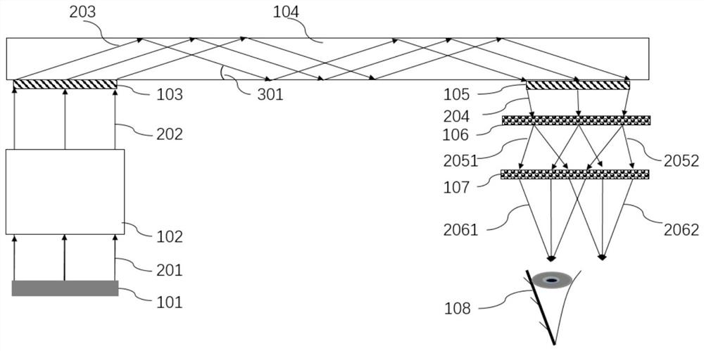
[0050] According to a preferred embodiment of the present invention, see figure 1 , providing a waveguide display system, characterized in that it comprises:
[0051] an image source 101, configured to generate an imaging beam 201;
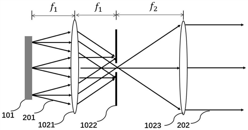
[0052] A relay collimation system 102, configured to collimate the imaging light beam 201 into a first parallel light 202 at the same angle;
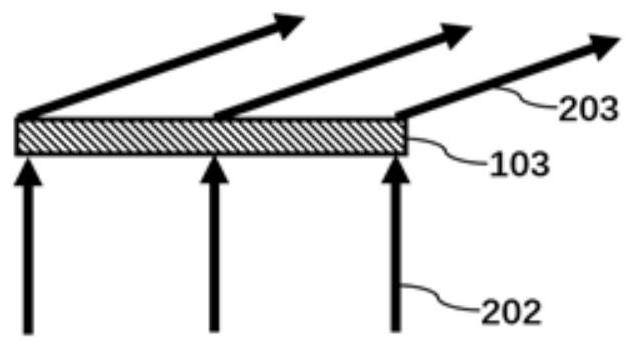
[0053] A coupler 103, configured to couple the first parallel light 202 into the following waveguide 104 to form a second parallel light 203;
[0054] a waveguide 104, configured to propagate the second parallel light 203 to the following coupler 105 in a manner of total reflection;
[0055] an output coupler 105, configured to diffract the second parallel light 203 into converging light 204, leave the waveguide 104, and enter the following first polarization grating 106;
[0056] The first polarization grating 106 is used to divide the converged light 204 into two beams of light emitted at different ang...
Embodiment approach
[0062] According to another preferred embodiment of the present invention, the image source 101 includes LCD, LCOS, DLP, OLED or laser scanning system.
[0063] According to yet another preferred embodiment of the present invention, the coupler 103 and the coupler 105 are reflective or transmissive.
[0064] According to yet another preferred embodiment of the present invention, the output coupler 105 outputs single or multiple convergent lights 204 .
[0065] According to yet another preferred embodiment of the present invention, the first polarization grating 106 and the output coupler 105 are arranged closely or at intervals.
[0066] According to yet another preferred embodiment of the present invention, there is also provided a waveguide 104 display method, which is characterized by comprising the following steps:
[0067] generating an imaging beam 201;
[0068] collimating the imaging light beam 201 into a first parallel light 202 at the same angle;
[0069] coupling...
Embodiment 2
[0078] According to a preferred embodiment of the present invention, see figure 1 A waveguide display system is provided, including an image source, a relay collimation system, a coupler, a waveguide, a coupler, and two polarization gratings of the same type and parallel to each other.
[0079] Wherein, the image source generates an imaging light beam, which is collimated into parallel light at the same angle through a relay collimation system.
[0080] The coupler couples the parallel imaging beam into the waveguide, and the reflection angle on the inner surface of the waveguide is larger than the total reflection angle, so it can propagate to the coupler through total reflection.
[0081] The imaging light is diffracted by the outcoupler into converging light and exits the waveguide.
[0082] The imaging light enters the first polarization grating, is split into two beams, and exits at different angles. The two beams of light are circularly polarized light with opposite rot...
PUM
 Abstract
Description
Claims
Application Information