Laser welding clamp and laser welding system

A laser welding fixture and laser welding technology, applied in laser welding equipment, welding equipment, welding equipment and other directions, can solve the problems of high welding cost and low welding efficiency, and achieve the effect of improving welding quality, simple structure and convenient installation.

Pending Publication Date: 2021-04-09
HANS LASER TECH IND GRP CO LTD +1
View PDF14 Cites 2 Cited by
  • Summary
  • Abstract
  • Description
  • Claims
  • Application Information

AI Technical Summary

Problems solved by technology

[0004] The invention solves the technical problems of low welding efficiency and high welding cost in vacuum welding of the clutch sun gear in the prior art, and provides a laser welding fixture, a laser welding machine and a laser welding system

Method used


Image

  • Laser welding clamp and laser welding system
  • Laser welding clamp and laser welding system
  • Laser welding clamp and laser welding system

Examples


Embodiment Construction

[0034]In order to make the technical problems, technical solutions and beneficial effects solved by the present invention, the present invention will be further detailed below with reference to the accompanying drawings and examples. It will be appreciated that the specific embodiments described herein are intended to explain the present invention and is not intended to limit the invention.

[0035]It is to be understood that the orientation or location relationship between the term "upper", "lower", "left", "right", "front", "latter", "middle", etc. is based on the orientation or location shown in the drawing. The relationship is intended to facilitate the description of the present invention and simplified description, rather than indicating or implying that the referred to means must have a specific orientation, and is constructed and operated in a particular direction, and thus is not to be understood as limiting.

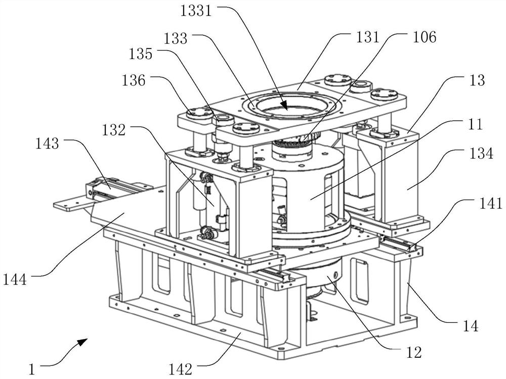
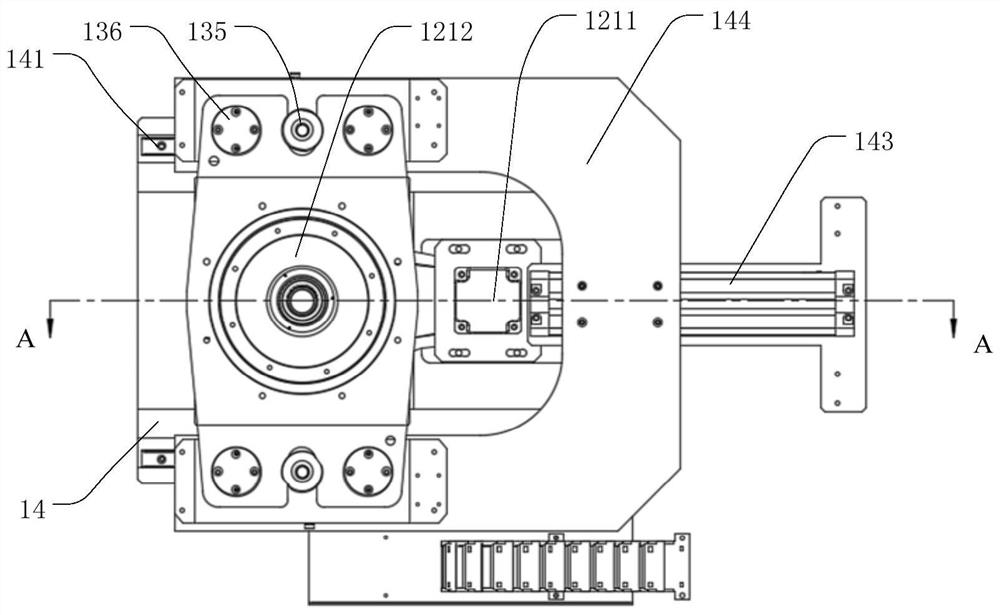
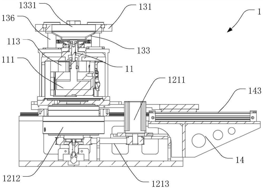
[0036]Such asFigure 1 to 3As shown, the laser welding jig 1 provided ...


PUM


Abstract

The invention belongs to the technical field of laser welding, and particularly relates to a laser welding clamp and a laser welding system. The laser welding clamp comprises an internal expansion clamping mechanism, a rotary driving mechanism, an anti-splashing mechanism and a base. The internal expansion clamping mechanism comprises a first telescopic piece and a single-cone expansion sleeve clamp used for installing, positioning and clamping a to-be-welded part. The single-cone expansion sleeve clamp penetrates through an inner hole of the to-be-welded part to be connected with a first telescopic part. The rotary driving mechanism comprises a rotary driving piece. The anti-splashing mechanism comprises a supporting plate, a second telescopic piece and an anti-splashing cover connected with the supporting plate and provided with a welding through hole. The second telescopic piece is installed on the base, and the supporting plate is installed on the second telescopic piece. The second telescopic piece drives the anti-splashing cover to ascend and descend above the to-be-welded piece through the supporting plate. According to the laser welding clamp, the structure is simple, installation is convenient, and the welding quality and the welding efficiency of the to-be-welded part are improved.

Description

Technical field[0001]The invention belongs to the field of laser welding technology, and more particularly to a laser welding clamp and a laser welding system.Background technique[0002]Automotive as the most common transportation, it has brought huge convenience to people's lives. The clutch sun gear is the main part in the automobile parking system, the clutch sun wheel is composed of a sun wheel that is welded to the solar wheel, and the welding precision of the clutch sunrift is high.[0003]In the prior art, the clutch sun gear usually achieves the connection between the sun gear and the sun, but the electron beam welding needs to be carried out in a vacuum environment, which is low, and the welding cost is high.Inventive content[0004]The present invention solves the low welding efficiency of the prior art in vacuum, welding cost, and a laser welding fixture and laser welding system.[0005]In view of the above problems, an embodiment of the present invention provides a laser weldin...

Claims


Application Information

Patent Timeline
Patent Type & Authority Applications(China)
IPC IPC(8): B23K26/70B23K37/04B23K26/28B23K26/08
CPCB23K26/702B23K37/0443B23K26/28B23K26/0884
Inventor 陈小冬潘佐梅唐景龙陈根余陈焱高云峰
Owner HANS LASER TECH IND GRP CO LTD
Why Eureka
Try Eureka