SCR rotational flow mixing pipe

A technology of swirling mixing and mixing tubes, which is applied in exhaust gas treatment, mechanical equipment, engine components, etc., can solve the problems of slow decomposition rate, uneven distribution, and high risk of crystallization of urea, so as to avoid wall contact crystallization and improve uniform distribution The effect of guaranteeing the uniformity of distribution

Active Publication Date: 2021-04-09
BEIJING INSTITUTE OF TECHNOLOGYGY
View PDF6 Cites 2 Cited by
  • Summary
  • Abstract
  • Description
  • Claims
  • Application Information

AI Technical Summary

Problems solved by technology

[0011] The purpose of the present invention is to solve the problems of uneven distribution of urea after spraying into the mixing tube, slow decomposition rate of urea, and high risk of crystallization caused by urea spray touching the wall in the mixing tube, and provide an SCR swirl mixing tube

Method used


Image

  • SCR rotational flow mixing pipe
  • SCR rotational flow mixing pipe
  • SCR rotational flow mixing pipe

Examples


Embodiment 1

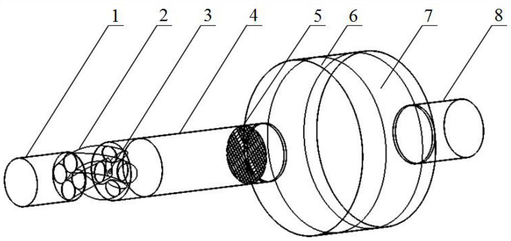
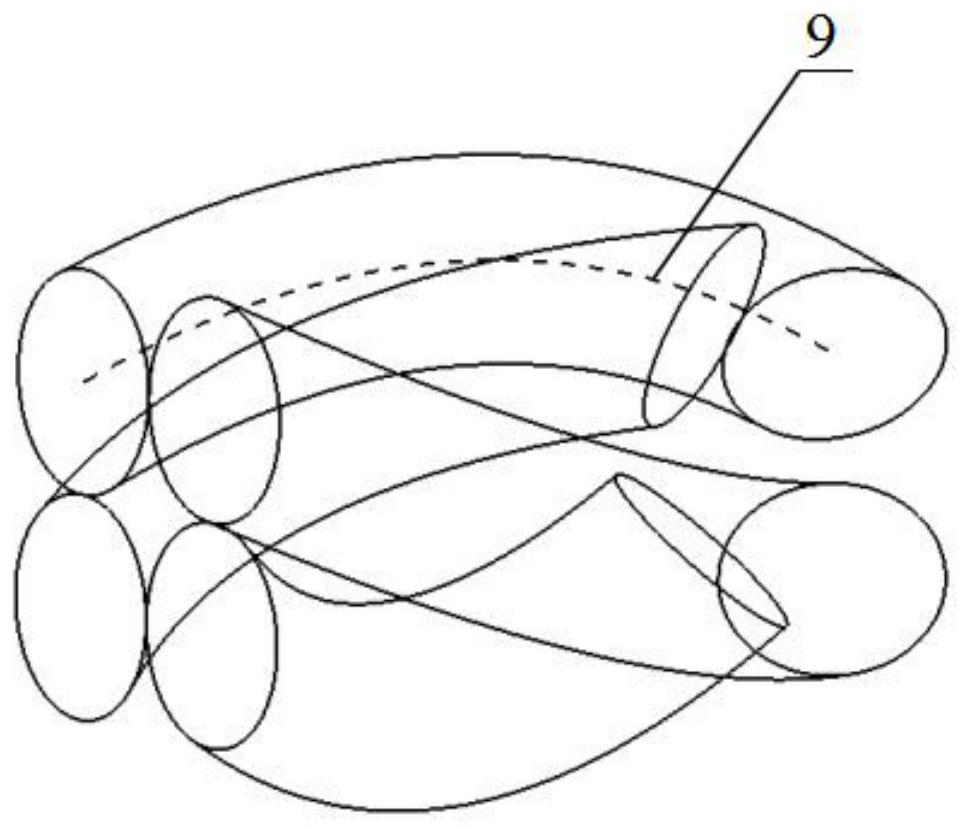
[0047] like Figure 1-4 As shown, a SCR swirl mixing tube is characterized in that: a spiral tube 2 is added between the intake pipe 1 and the mixing tube 4, and a space is generated in the front section of the mixing tube 4, and a urea injector 3 can be installed; the spiral tube 2 makes the discharge The air rotates, creating turbulence. Then it is rectified by the post-mixer 5 to improve the distribution uniformity of urea and its decomposition products again. Finally, the mixed gas undergoes NOx reduction reaction on the SCR catalyst 7 in the reactor barrel 6, and the treated exhaust gas finally passes through the Exhaust pipe 8 discharges.

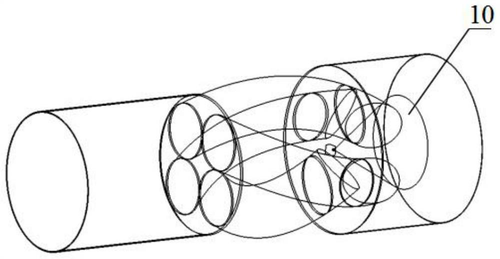
[0048] By using the spiral tube 2, an installation space is created on the front section of the mixing tube 4, and the urea injector 3 and its control lines can be arranged. This structure can make the urea evenly sprayed into the mixing tube 4, and the cylindrical urea spray mist beam 10 and The circular mixing tube 4 is optimally ...

Embodiment 2

[0057] The device is the same as in Embodiment 1, except that the distance D=400mm between the urea injection point and the front end face of the mixing tube 4, as Figure 5 shown.

[0058] Now only a small part of the swirling air flow will directly act on the urea spray mist beam 10, most of the swirling air flow directly generates a protective air flow on the wall of the mixing tube 4, the urea injection position moves backward, and the position where the urea spray may touch the wall also Correspondingly move back, the position of contacting the wall after the move back has better protective airflow, stronger swirling airflow can better carry away the urea sprayed to the wall of the mixing tube, and the anti-crystallization ability is stronger.

Embodiment 3

[0060] The device is the same as in Embodiment 1, except that the distance D=800mm between the urea injection point and the front end face of the mixing tube 4, as Image 6 shown.

[0061] At this time, all the swirling airflows directly generate protective airflows on the walls of the mixing tube 4, and no swirling airflows directly act on the urea spray mist beam 10. The possible wall-touching position of the urea spraying moves backwards with the urea injection point, and the wall-touching position after the backward movement A large number of protective airflows are formed at the position, and the strong swirling airflow can directly carry away the urea sprayed to the inner wall of the mixing tube 4, and has strong anti-crystallization ability.


PUM


Abstract

The invention relates to an SCR rotational flow mixing pipe, and belongs to the technical field of engine aftertreatment. The invention aims to solve the problems of non-uniform distribution after urea is sprayed into a mixing pipe, low urea decomposition rate, high crystallization risk caused by urea spray wall contact in the mixing pipe, and the like. According to a spiral pipe structure of the SCR rotational flow mixing pipe, turbulence can be formed in the mixing pipe at the rear end, so that the decomposition rate of the urea in the mixing pipe is increased, and the urea crystallization risk is reduced. Meanwhile, rotating airflow generated by the spiral pipe structure can form a large amount of rotating airflow around the inner wall of the mixing pipe, and the urea solution sprayed to the inner wall of the mixing pipe is carried away, so that the urea crystallization risk is further reduced; and urea spraying points of the SCR rotational flow mixing pipe are arranged in the middle, so that the distribution uniformity of the urea in the mixing pipe can be improved, and finally the NOX conversion efficiency of an SCR system is improved. The urea spraying points are arranged in the middle to be matched with the mixing pipe with the rear end increasing the pipe diameter, so that the urea solution can be effectively prevented from contacting the wall, and the urea crystallization risk is reduced.

Description

technical field [0001] The invention relates to an SCR swirl mixing tube, which belongs to the technical field of engine aftertreatment. Background technique [0002] SCR technology can effectively solve the NO of diesel engine X To solve the emission problem, this technology has been widely used in the National IV and National V stages of vehicle diesel engines. The basic working principle of SCR is to inject reducing agent into the exhaust pipe of diesel engine through the urea injection system, and the reducing agent reacts with NOx under the action of the catalyst to convert NOx into N 2 , for NOx emission control, in diesel engine NOx, more than 90% of the components are NO and NO 2 . The commonly used reducing agent in SCR technology is NH 3 , usually by spraying urea into the exhaust pipe, the urea is decomposed to obtain NH 3 . [0003] Formula (1) shows that the injected urea decomposes endothermicly to produce NH 3 , formula (2) and formula (3) represent NH ...

Claims


Application Information

Patent Timeline
Patent Type & Authority Applications(China)
IPC IPC(8): F01N3/28F01N3/20
CPCF01N3/2066F01N3/2892F01N2610/02F01N2610/1453Y02T10/12
Inventor 王文晓左正兴
Owner BEIJING INSTITUTE OF TECHNOLOGYGY
Why Eureka
Try Eureka