
Liquid hydrogen evaporated gas treatment system and control method thereof

A treatment system and evaporated gas technology, applied in the direction of gas treatment/storage, gas treatment/storage effect, fluid treatment, etc., can solve problems such as expensive liquefaction equipment, lack of control functions, and increased cost of ship construction to improve safety and stability, efficient and orderly regulation, and the effect of reducing ship cost

Active Publication Date: 2021-04-09
JIANGNAN SHIPYARD GRP CO LTD
View PDF10 Cites 1 Cited by
  • Summary
  • Abstract
  • Description
  • Claims
  • Application Information

AI Technical Summary

Problems solved by technology

Usually there are two ways to deal with it. One is to guide the evaporated gas out of the storage tank and then carry out reliquefaction treatment. However, due to the extremely low liquefaction temperature of the evaporated gas, the liquefaction equipment for reliquefying the evaporated gas is extremely expensive; the second is to liquefy the evaporated gas. Confined in the liquid hydrogen storage tank and not discharged, but this will definitely increase the internal pressure of the storage tank, causing safety hazards. If the design pressure of the storage tank is blindly increased, the cost of the ship will also be greatly increased
In addition, the method of limitation and recovery mentioned above lacks the regulation and control function, and it is difficult to keep the pressure in the storage tank stable.

Method used


Image

  • Liquid hydrogen evaporated gas treatment system and control method thereof
  • Liquid hydrogen evaporated gas treatment system and control method thereof
  • Liquid hydrogen evaporated gas treatment system and control method thereof

Examples


Embodiment Construction

[0069] Embodiments of the present invention are described below through specific examples, and those skilled in the art can easily understand other advantages and effects of the present invention from the content disclosed in this specification. The present invention can also be implemented or applied through other different specific implementation modes, and various modifications or changes can be made to the details in this specification based on different viewpoints and applications without departing from the spirit of the present invention.

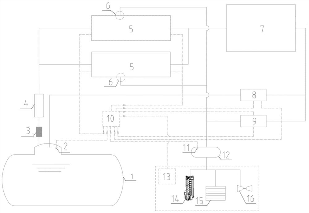
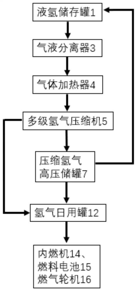
[0070] This embodiment provides a liquid hydrogen vapor processing system, such as figure 1 As shown, the processing system specifically includes the following components:

[0071] Liquid hydrogen storage tank 1, a low-temperature container for storing liquid hydrogen, stores hydrogen in a liquid form at atmospheric pressure and fully cooled (-253°C), and is the original storage location for liquid hydrogen;

[0072] The first pressu...


PUM


Abstract

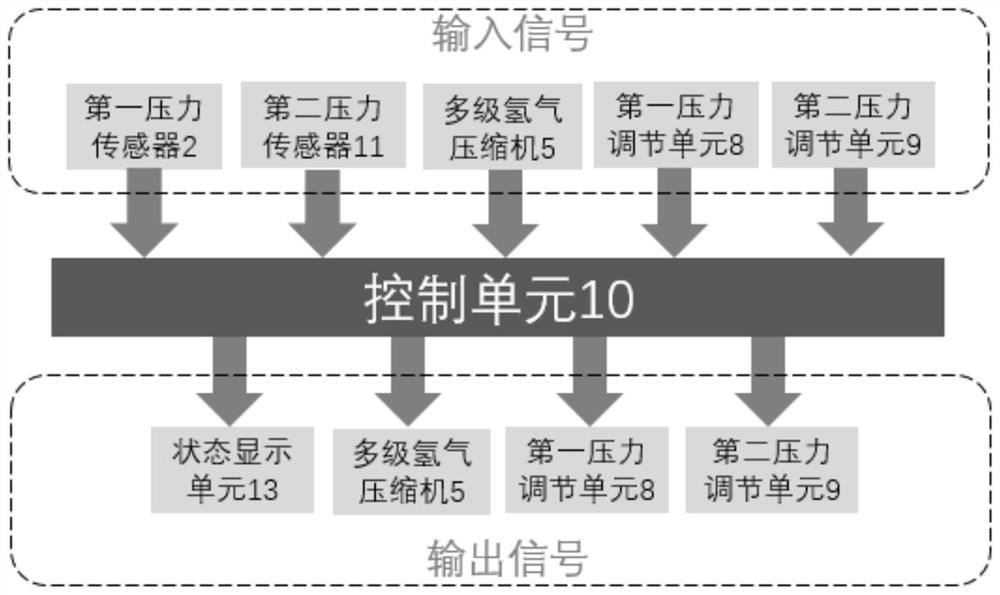
The invention provides a liquid hydrogen evaporated gas treatment system and a control method thereof. Reasonable guiding and utilization of liquid hydrogen evaporated gas in a liquid hydrogen transport ship are achieved, the evaporated gas in the liquid hydrogen storage tank can be stored in a hydrogen daily tank to be supplied to daily equipment after being compressed by a multi-stage hydrogen compressor, and can also be stored in a compressed hydrogen high-pressure storage tank, loss caused by the fact that evaporated gas is directly exhausted into the atmosphere is avoided, expensive liquefaction equipment is not needed, and the ship manufacturing cost is greatly reduced. Wherein the compressed hydrogen high-pressure storage tank simultaneously has storage and supply buffer functions, evaporated gas stored in the compressed hydrogen high-pressure storage tank can be supplied to the hydrogen daily tank and can also be supplied to the liquid hydrogen storage tank, and a key effect on maintaining the stability of the whole system is achieved. A control unit realizes real-time regulation and control of the whole system, and cooperates with the compressed hydrogen high-pressure storage tank to always keep the internal pressure of the liquid hydrogen storage tank and the hydrogen daily tank stable, so that the safety and stability in ship transportation are greatly improved, and extremely high practical value is achieved.

Description

technical field [0001] The invention relates to the field of liquid hydrogen transport ships, in particular to a liquid hydrogen evaporation gas processing system and a control method thereof. Background technique [0002] With the increasing energy crisis and environmental pollution, in April 2018, IMO formulated a strategy for reducing greenhouse gas emissions. Hydrogen, as a carbon-free clean energy, is one of the new fuels that is currently receiving much attention and vigorously developed by the shipping industry. New concept ships such as liquid hydrogen carriers and hydrogen fuel-powered ships have also emerged as the times require, and have become popular research directions in the industry. The most critical point is how to store and transport liquid hydrogen. [0003] The storage of hydrogen on board is usually stored in a liquid hydrogen storage tank in the form of a fully cooled (-253°C) liquid at atmospheric pressure. In the process of loading, filling, and t...

Claims


Application Information

Patent Timeline
Patent Type & Authority Applications(China)
IPC IPC(8): F17C3/02F17C1/00F17C5/06F17C7/00F17C9/02F17C13/00F17C13/02F17C13/04F17D1/04F17D1/07F17D3/01F17D1/20F17D5/00
CPCF17C3/025F17C1/002F17C5/06F17C7/00F17C9/02F17C13/00F17C13/025F17C13/04F17D1/04F17D1/07F17D3/01F17D1/20F17D5/005F17C2205/0134F17C2205/0323F17C2205/0338F17C2221/012F17C2223/0123F17C2223/0161F17C2225/0123F17C2227/0157F17C2250/043F17C2260/031F17C2260/046F17C2265/036F17C2265/037F17C2270/0105Y02P90/45Y02E60/34Y02E60/32
Inventor 张道志周鑫元郑双燕李晓姣秦斌
Owner JIANGNAN SHIPYARD GRP CO LTD
Learn More