
Device for detecting gas components

A technology for detecting gases and gases, applied in measurement devices, analysis materials, material analysis by optical means, etc., can solve the high initial cost and maintenance cost of optical path design, increase the overall cost of the detection device, and affect the cleanliness of the gas under inspection. To achieve the effect of achieving continuity and high real-time, avoiding potential pollution and direct impact, and improving sensitivity and accuracy

Pending Publication Date: 2021-04-09
HEFEI INST FOR PUBLIC SAFETY RES TSINGHUA UNIV +2
View PDF0 Cites 0 Cited by
  • Summary
  • Abstract
  • Description
  • Claims
  • Application Information

AI Technical Summary

Problems solved by technology

However, the complexity of optical path design often brings high initial cost and maintenance cost
In addition, in the traditional detection device, the optical path components are directly installed in the gas under test, which easily affects the cleanliness of the gas under test and thus seriously affects the detection effect. It also needs to add pre-treatment structures and processes such as gas dust removal and dehumidification, which greatly improves the The overall cost of the detection device; at the same time, in addition to the solid / liquid suspended particles in the gas, components with corrosive effects are also key factors that affect the life of the optical path components in the detection device and even the entire machine

Method used


Image

  • Device for detecting gas components

Examples


Embodiment 1

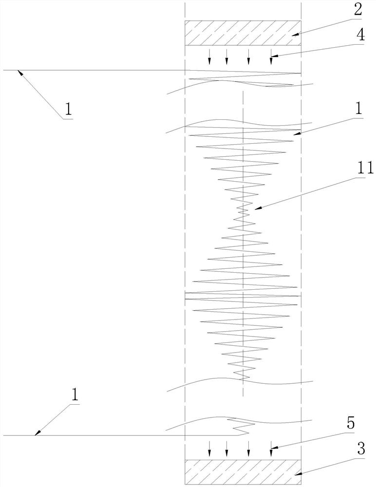
[0027] A device for detecting gas components, comprising a smooth and transparent gas pipeline 1 in the middle, and optical path components, the optical path components are used to illuminate and detect the gas in the gas pipeline 1 in the middle, and the two ends of the gas pipeline 1 As the gas inlet and the gas outlet respectively, the optical path component and the gas pipeline 1 are independent of each other.

[0028] The optical path components include a light source 2 and a detector 3, the light generated by the light source 2 passes through the gas pipeline 1 in the middle and hits the detector 3, and the projection of the gas pipeline 1 in the middle in the direction of the light source 2 falls on the On the light source 2 in the optical path components. The two ends and the middle part of the gas pipeline 1 are integrated composite structures. Ensure the fluency of gas.

[0029] In this embodiment, the gas pipeline 1 is linear, the light source 2 is arranged direct...

Embodiment 2

[0031] The difference from Embodiment 1 is that in this embodiment, the gas pipeline 1 in the middle is in the shape of a planar coil. For the convenience of processing, it is specifically a planar spiral shape. The diameter / length of the gas line 1 is 1 / 40.

Embodiment 3

[0033] The difference from Embodiment 1 is that in this embodiment, the gas pipeline 1 in the middle is in a three-dimensional coiled shape. Specifically, it is a three-dimensional spiral shape. The diameter / length of the gas line 1 is 1 / 30. The light source 2 is annular.


PUM


Abstract

The invention belongs to the field of gas environment monitoring equipment, and particularly relates to a device for detecting gas components. The device comprises a gas pipeline with a smooth and transparent middle part and an optical path component, the optical path component is used for irradiating and detecting gas in the gas pipeline in the middle, the two ends of the gas pipeline are respectively used as an inlet and an outlet of the gas, and the optical path component and the gas pipeline are independent of each other. The device has the advantages that: the gas pipeline and the optical component are independent from each other, and the detected gas is completely sealed in the pipeline, so that the pollution and impact effects of the detected gas on the optical component are fundamentally avoided, the service life of the device is prolonged, and the operation and maintenance cost is reduced. Compared with a gas chamber structure of traditional equipment and intermittent sampling characteristics thereof, the device uses a gas pipeline with a smooth and transparent middle part, so that continuous and smooth sampling of detected gas can be ensured, and the continuity and high real-time performance of a detection process are further realized; and meanwhile, impact noise and vibration can be reduced, and the stability of the detection process and the accuracy of detection results are improved.

Description

[0001] This application claims a divisional application of "a gas component detection device" with the application number 201811223535.X filed on October 19, 2018, and the original acceptance institution is in China. technical field [0002] The invention relates to the field of gas environment monitoring equipment, in particular to a device for detecting gas components. Background technique [0003] Gas sampling channel (referred to as gas circuit) and gas detection chamber (referred to as gas chamber) are common structures in devices used to detect gas components. Among them, the gas chamber is the core component of the detection device, and the gas circuit is usually used to sample the environment. Gas input and output gas chamber. During the working process of the traditional detection device, the gas to be tested enters the gas chamber through the gas path by autonomous diffusion or external force, and emits a characteristic spectrum under the illumination of the light ...

Claims


Application Information

Patent Timeline
Patent Type & Authority Applications(China)
IPC IPC(8): G01N21/84G01N21/01
CPCG01N21/01G01N21/84G01N2021/0112
Inventor 朱友平付明张泽玮杨广
Owner HEFEI INST FOR PUBLIC SAFETY RES TSINGHUA UNIV
Learn More