Supercharge Your Innovation With Domain-Expert AI Agents!

A lock-in amplifier suitable for laser frequency locking

A lock-in amplifier and frequency locking technology, which is applied to amplifiers, lasers, amplifier types, etc., can solve the problems of inability to realize independent adjustment of the monitored error signal, inability to achieve phase shift and continuous gain adjustment, and high cost, achieving ingenious design, Reasonable structure and low cost

Active Publication Date: 2022-07-19
怡升科技(大连)有限公司
View PDF6 Cites 0 Cited by
  • Summary
  • Abstract
  • Description
  • Claims
  • Application Information

AI Technical Summary

Problems solved by technology

[0003] In order to solve the problem that the existing commercial lock-in amplifier operating frequency range or optimal operating frequency range does not necessarily include the modulation frequency of the error signal, the continuous adjustment of the phase shift and gain cannot be realized, the independent adjustment of the monitored error signal cannot be realized, and the cost is high. problem, a lock-in amplifier suitable for laser frequency locking is provided

Method used


Image

  • A lock-in amplifier suitable for laser frequency locking
  • A lock-in amplifier suitable for laser frequency locking

Examples


Embodiment Construction

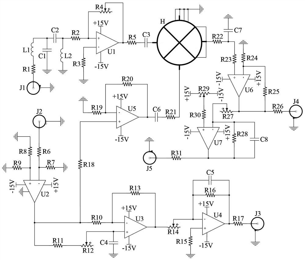
[0024] A lock-in amplifier suitable for laser frequency locking, comprising a first BNC connector J1, a first resistor R1, a first LC filter circuit, a second LC filter circuit, a first non-inverting amplifier circuit, a first RC filter circuit, a mixed Frequency converter H, second BNC connector J2, isolation circuit, phase shift circuit, first inverting amplifier circuit, seventeenth resistor R17, third BNC connector J3, second inverting amplifier circuit, second RC filter circuit, first Three RC filter circuits, the second non-inverting amplifier circuit, the twenty-sixth resistor R26, the fourth BNC connector J4, the bias amplifier circuit, the thirty-first resistor R31, and the fifth BNC connector J5;

[0025] The first LC filter circuit includes a first inductor L1 and a first capacitor C1; the second LC filter circuit includes a second capacitor C2 and a second inductor L2; the first non-inverting amplifying circuit includes a second resistor R2, A third resistor R3, a ...


PUM


Abstract

The invention relates to a laser frequency locking technology, in particular to a phase-locking amplifier suitable for laser frequency locking. It solves the problems that the operating frequency range or optimal operating frequency range of the existing commercial lock-in amplifier does not necessarily include the modulation frequency of the error signal, the continuous adjustment of phase shift and gain cannot be realized, the independent adjustment of the monitored error signal cannot be realized, and the cost is high. . A lock-in amplifier suitable for laser frequency locking includes a first BNC connector, a first resistor, a first LC filter circuit, a second LC filter circuit, a first non-inverting amplifier circuit, a first RC filter circuit, a mixer, The second BNC connector, the isolation circuit, the phase shift circuit, the first inverting amplifier circuit, the seventeenth resistor, the third BNC connector, the second inverting amplifier circuit, the second RC filter circuit, the third RC filter circuit, the second Non-inverting amplifier circuit, twenty-sixth resistor, fourth BNC connector, bias amplifier circuit, thirty-first resistor, fifth BNC connector. The present invention is suitable for laser frequency locking.

Description

technical field [0001] The invention relates to a laser frequency locking technology, in particular to a phase-locked amplifier suitable for laser frequency locking. Background technique [0002] With the continuous development and innovation of laser technology, laser has been widely used in industry, medical, military, precision measurement and communication. In practical applications, in order to overcome the influence of environmental temperature, external mechanical vibration and other factors on the laser frequency, the laser frequency is often locked to the resonance transition frequency of atoms, molecules or F-P cavity. However, before locking the laser frequency, a lock-in amplifier needs to be used to modulate and demodulate the absorption signal containing the resonant transition frequency of atoms, molecules or F-P cavity, so as to output the error signal for locking the laser frequency. Under the existing technical conditions, commercial lock-in amplifiers gen...

Claims


Application Information

Patent Timeline
Patent Type & Authority Patents(China)
IPC IPC(8): H03F7/00H03L7/00H01S3/13H01S5/068
CPCH03F7/00H03L7/00H01S3/13H01S5/068
Inventor 李玉清王晓锋马杰肖连团贾锁堂
Owner 怡升科技(大连)有限公司
Features
  • R&D
  • Intellectual Property
  • Life Sciences
  • Materials
  • Tech Scout
  • Unparalleled Data Quality
  • Higher Quality Content
  • 60% Fewer Hallucinations
Learn More