Welding strip section conveying mechanism and diamond saw blade welding machine
A technology of conveying mechanism and welding strip, which is applied in welding equipment, tin feeding device, metal processing equipment, etc. It can solve the problems of slow processing efficiency and easy drop, and achieve the effects of low cost, improved welding quality and stable work
- Summary
- Abstract
- Description
- Claims
- Application Information
AI Technical Summary
Problems solved by technology
Method used
Image

Examples
Embodiment 1
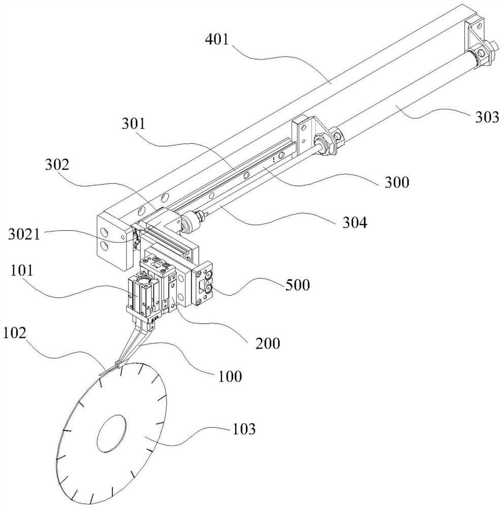
[0023] A transporting mechanism for a welding ribbon section includes a pair of synchronous pneumatic grippers 100 for clamping the inner side and the outer side of a welding ribbon section 102 . The inner side and the outer side specifically refer to two sides of the welding strip segment 102 parallel to the plane of the saw blade base 103 . The synchronous pneumatic gripper 100 has a cylinder body 101 and two sliding heads, each of which is fixedly connected with a gripper 100 ; the cylinder body 101 is fixedly connected to the movable end of a lifting drive mechanism 200 . The mechanism is also provided with a transverse drive mechanism 300 that can move the clamped welding strip section 102 to the top of the saw blade 103 substrate to be welded, and the transverse drive mechanism 300 is fixed on the frame 400 . Taking the saw blade 103 as an example, the sawtooth of the saw blade 103 to be welded is the outer peripheral top area of the circular saw blade base. Similarly...
Embodiment 2
[0030] The structure and principle of this embodiment are basically the same as that of Embodiment 1, and the similarities will not be described in detail, but only the differences will be described. There is a longitudinal drive mechanism 500 capable of moving the synchronous pneumatic gripper 100 towards a direction perpendicular to the guiding direction of the transverse drive mechanism 300 . The longitudinal driving mechanism 500 is a double-piston rod sliding table cylinder, the cylinder body of which is fixedly connected to the movable end of the horizontal driving mechanism 300 through the connecting seat 3021 , and its sliding body is fixed on the housing of the lifting driving mechanism 200 through a connecting plate 501 . The purpose of providing the longitudinal driving mechanism 500 is to expand and adjust the conveying area of the transverse driving mechanism 300 and improve the application range of the ribbon section conveying mechanism.
Embodiment 3
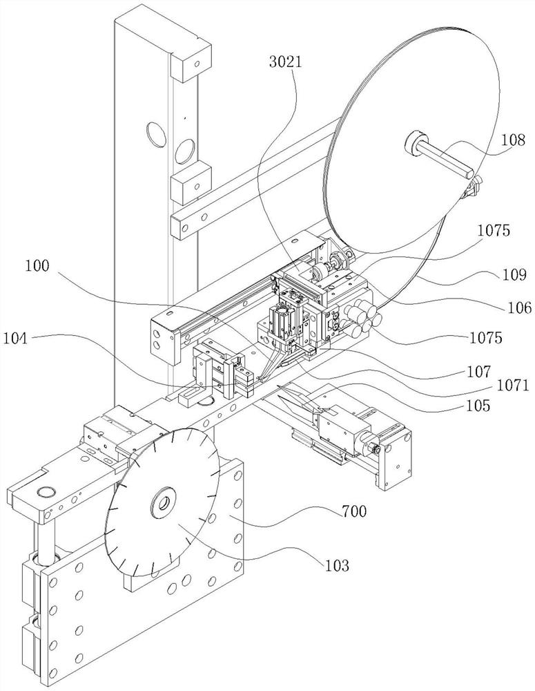
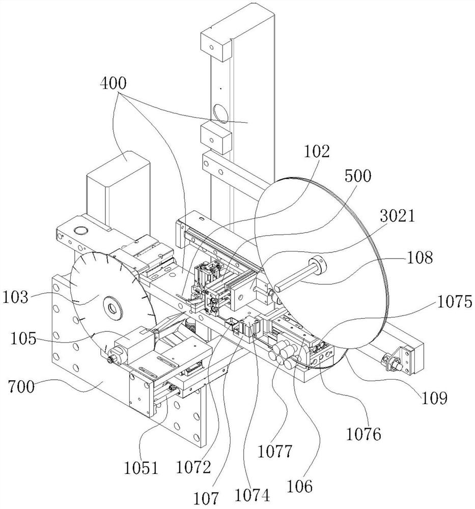
[0032]The diamond saw blade welding machine manufactured according to the technical solution of Example 1 includes a welding belt section conveying mechanism, a saw blade base body positioning mechanism 700 is arranged below the frame 400, and a knife is arranged directly above the saw blade base body positioning mechanism 700. The head clamping positioning mechanism, the right side of the frame 400 is provided with a welding strip section supply mechanism.
[0033] The welding ribbon segment supply mechanism includes the welding ribbon 109 and the fixing bracket 108 for fixing the welding ribbon, and the welding ribbon mechanism 106 that pulls out the free end of the welding ribbon 109 from the fixing bracket 108 and straightens it. The free end of the welding band 109 is pulled out from the fixed bracket 108 and the push welding band mechanism 106 for straightening; the guide seat 107 that makes the welding band 109 horizontally orientate the output to the saw blade base dire...
PUM
 Abstract
Description
Claims
Application Information
 - R&D
- Intellectual Property
- Life Sciences
- Materials
- Tech Scout
- Unparalleled Data Quality
- Higher Quality Content
- 60% Fewer Hallucinations
Browse by: Latest US Patents, China's latest patents, Technical Efficacy Thesaurus, Application Domain, Technology Topic, Popular Technical Reports.
© 2025 PatSnap. All rights reserved.Legal|Privacy policy|Modern Slavery Act Transparency Statement|Sitemap|About US| Contact US: help@patsnap.com