Gantry crane box girder wind resistance and load reduction bionic structure and design method thereof
A gantry crane and box girder technology, which is applied in the directions of support structure, bottom support structure, design optimization/simulation, etc., can solve the special case study of unsystematic, blank design of wind resistance and load reduction, and no systematic study to reveal the characteristics of wind-induced effects of cranes And other issues
- Summary
- Abstract
- Description
- Claims
- Application Information
AI Technical Summary
Problems solved by technology
Method used
Image
Examples
Embodiment 1
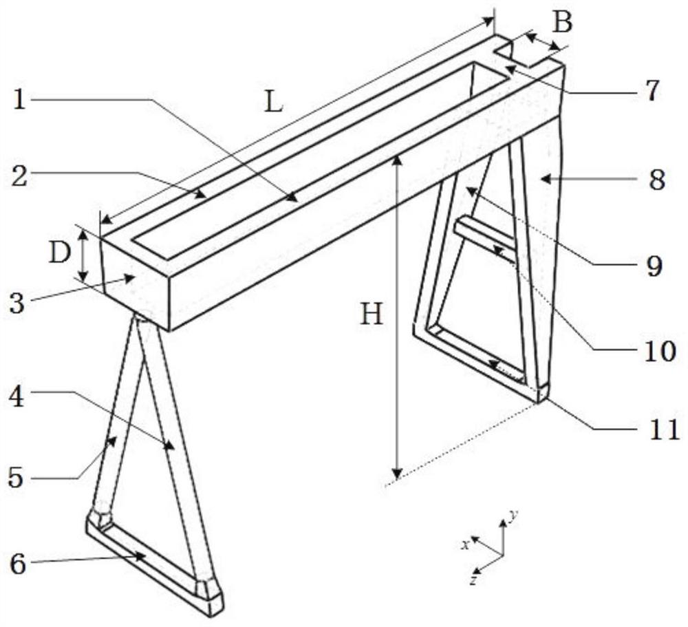
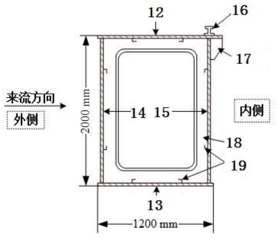
[0090] In this field, the main girder of a gantry crane generally adopts a box girder structure with a rectangular or trapezoidal section. figure 2A box girder structure of a 40t container gantry crane is given. The box girder of the gantry crane is mainly composed of the upper flange plate 12, the lower flange plate 13, the left web 14 and the right web 15 to form the main body of the box girder. 19 to enhance the local stability of the main girder; the top of the upper flange plate 12 is provided with a trolley track 16, and the trolley track is mostly located on the main web of the box girder (deviating track) or in the middle of the box girder (normal track) to make the overall bearing stability of the box girder ; When the trolley track is located on the main web of the box girder ( figure 2 When being on the right web 15) in the middle, the ear plate 17 for hoisting is arranged below the upper flange plate at its corresponding position.
[0091] The outer web of the ...
Embodiment 2
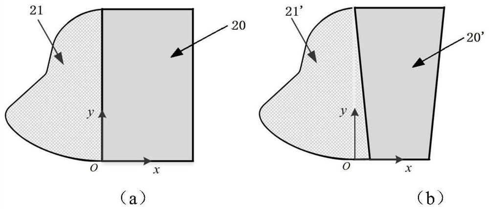
[0095] The width direction of the box girder of the gantry crane is X, the height direction is Y, and the longitudinal length direction of the box girder is Z direction. Without considering the change in the Z direction, the height of the crane box girder is used as the design variable, and the mathematical model of the X-Y section is obtained by fitting the profile of the mouth of the fish grained boxfish, and then the grained boxfish is constructed on the windward side of the box girder The bionic structure model of the mouth is obtained to obtain the bionic outline.
[0096] However, since the girder of the gantry crane is generally long, it is difficult to achieve a better effect by simply fitting the profile generated by the bionic boxfish mouth without considering the change in the Z direction.
[0097] like Figure 4-Figure 6 As shown, in this embodiment, the cross-section of the boxfish mouth bionic structure 3 perpendicular to the length direction of the box girder i...
Embodiment 3
[0145] Taking the 40t container gantry crane provided in Embodiment 1 as an example, this embodiment provides a method for manufacturing the bionic structure of the gantry crane box girder wind resistance and load reduction provided in Embodiment 2, including the following steps:
[0146] The first step is to obtain the structural parameters of the gantry crane box girder, including the length of the box girder and the height of the box girder; in this embodiment, the height D of the box girder is 2 m, and the length L of the box girder is 40 m.
[0147] In the second step, according to the design method in Example 2, the contour model of the bionic carrier (ie, the bionic structure of the boxfish mouth) is obtained.
[0148] The third step is to use polystyrene foam as the substrate, and process and shape the bionic structure attachment material according to the contour model of the obtained bionic carrier (that is, the bionic structure of the boxfish mouth bionic structure); ...
PUM
 Abstract
Description
Claims
Application Information
 - R&D
- Intellectual Property
- Life Sciences
- Materials
- Tech Scout
- Unparalleled Data Quality
- Higher Quality Content
- 60% Fewer Hallucinations
Browse by: Latest US Patents, China's latest patents, Technical Efficacy Thesaurus, Application Domain, Technology Topic, Popular Technical Reports.
© 2025 PatSnap. All rights reserved.Legal|Privacy policy|Modern Slavery Act Transparency Statement|Sitemap|About US| Contact US: help@patsnap.com


