Active fault crossing tunnel seismic reduction joint structure, tunnel structure and construction method

A technology of active faults and construction methods, applied in tunnels, tunnel linings, earthwork drilling and mining, etc., can solve problems such as low loose strength of rock mass in fault fracture zones, poor structural continuity, and damage to anti-seepage systems, and achieve energy dissipation The shock absorption is effective and reasonable, the large displacement is reduced, and the effect of direct action is slowed down

Pending Publication Date: 2021-04-16
INST OF ROCK & SOIL MECHANICS CHINESE ACAD OF SCI
View PDF5 Cites 2 Cited by
  • Summary
  • Abstract
  • Description
  • Claims
  • Application Information

AI Technical Summary

Problems solved by technology

[0004] In this technical field, setting damping joints in the area where the tunnel passes through the active fault zone can effectively reduce the stress of longitudinal seismic wave propagation, but at the same time it also makes the structural continuity worse, making the lining an independent unit, and because the rock mass in the fault fracture zone is loose The strength is low, and the lining cannot be given sufficient constraints, resulting in a relatively large absolute displacement of the tunnel under the earthquake, and in severe cases, permanent displacement deformation of the tunnel after the earthquake
At the same time, the joints in the tunnel deform greatly during the earthquake. Although it can effectively consume energy and absorb shocks, there is a common problem of damage to the anti-seepage system.

Method used


Image

  • Active fault crossing tunnel seismic reduction joint structure, tunnel structure and construction method
  • Active fault crossing tunnel seismic reduction joint structure, tunnel structure and construction method
  • Active fault crossing tunnel seismic reduction joint structure, tunnel structure and construction method

Examples


Embodiment 1

[0039] This embodiment provides a shock-absorbing joint structure for tunnels across active faults, such as Figure 4 with Figure 5 As shown, for the longitudinal section I-I of a fault dislocation part, including the rubber layer I-5, the rubber layer I-5 is set in the shock-absorbing joint, and the rubber layer I-5 is subjected to large deformation, and the seismic energy is consumed through the deformation to improve Circumferential deformation tolerance of cross-fault parts. Rubber layer I-5 longitudinal (with Figure 4 The horizontal direction is longitudinal) located between the concrete I-14 of the first construction section and the concrete I-15 of the subsequent construction section, and the circumferential direction is located between the inner steel plate I-8 of the shock-absorbing joint and the outer steel plate I-9 of the shock-absorbing joint .

[0040] Further, the rubber layer I-5 is connected with the concrete I-14 of the first construction section and the...

Embodiment 2

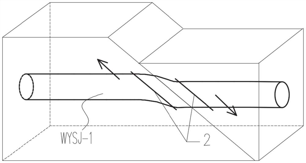
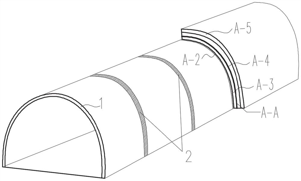
[0051] This embodiment provides a tunnel structure across active faults, taking the tunnel construction section WYSJ-1 as an example, as Figure 1-Figure 3 As shown, it includes the secondary lining layer 1 of the tunnel construction section, and the shock-absorbing layer 2 of the tunnel construction section distributed along the longitudinal interval of the tunnel.

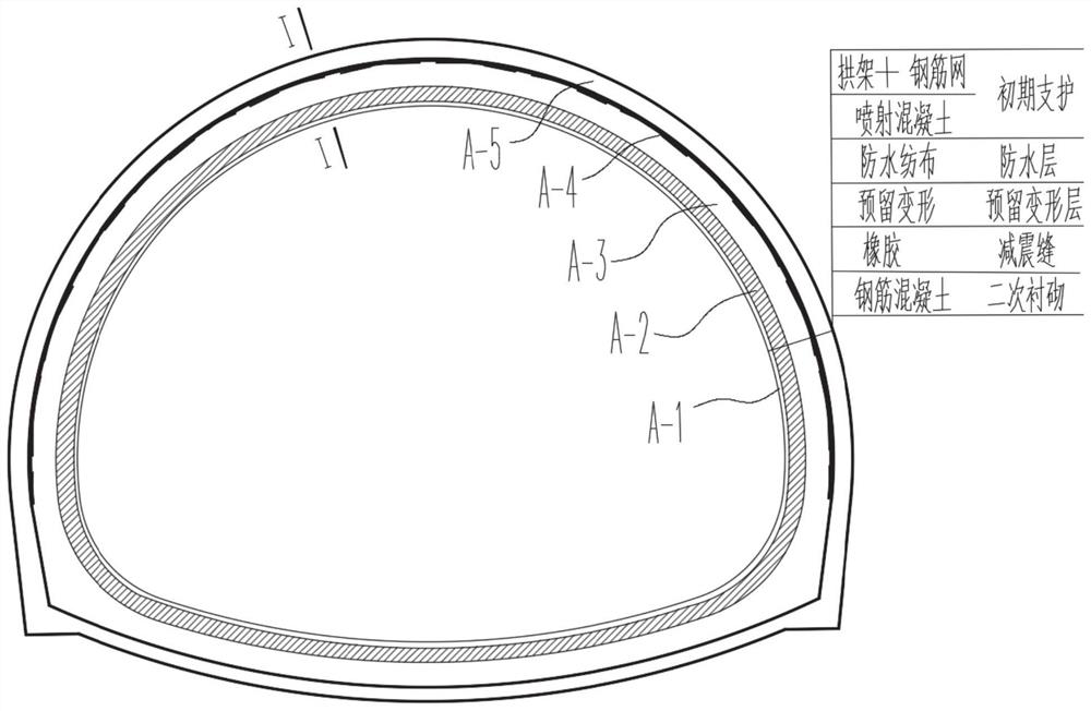
[0052] The fault-crossing part of the tunnel is prone to large displacement and dislocation under the action of an earthquake, which will lead to excessive stress and damage of the tunnel structure or excessive deformation and affect normal use. coming adverse effects. For the cross-section A-A of any fault-crossing part of the tunnel, the secondary lining layer A-1 of the section, the shock-absorbing layer A-2 of the section, the reserved deformation layer A-3 of the section, the waterproof layer A-4 of the section, and the Primary support layer A-5.

[0053] This embodiment adopts the method of shock absorbin...

Embodiment 3

[0059] This embodiment provides a construction method for the construction of a waterproof shock-absorbing joint for a cross-fault tunnel, including:

[0060] S1: Preparatory work: Put the rubber layer I-5, the inner steel plate I-6 in the first construction section, the inner steel plate I-8 in the damping joint, the inner steel plate I-7 in the later construction section, and the outer steel plate I- in the first construction section. 16. The outer steel plate I-9 of the shock-absorbing joint and the outer steel plate I-17 of the post-construction section are treated in advance (including derusting the surface of the steel plate, grinding the outer edges and corners, and painting the surface). Specifically, as follows:

[0061] (1) Advance treatment of rubber layer I-5:

[0062] The surface of the rubber layer I-5 is treated by grinding method. First, the surface is cleaned with methanol, then ground with fine sand, then cleaned with methanol, and dried.

[0063] (2) Steel...


PUM


Abstract

The invention discloses an active fault crossing tunnel seismic reduction joint structure, a tunnel structure and a construction method. The technical solution of the active fault crossing tunnel seismic reduction joint structure comprises a rubber layer arranged in a seismic reduction joint, the rubber layer is longitudinally located between pre-construction section concrete and post-construction section concrete, the rubber layer is annularly located between a seismic reduction joint inner layer steel plate and a seismic reduction joint outer layer steel plate, one end of the seismic reduction joint inner layer steel plate is fixed with a pre-construction section inner layer steel plate, the other end is fixed with a post-construction section inner layer steel plate, one end of the seismic reduction joint outer layer steel plate is fixed with a pre-construction section outer layer steel plate, the other end is fixed with a post-construction section outer-layer steel plate, and reinforcing meshes are installed between the pre-construction section inner layer steel plate and the pre-construction section outer layer steel plate and between the post-construction section inner layer steel plate and the post-construction section outer layer steel plate correspondingly. According to the active fault crossing tunnel seismic reduction joint structure, the tunnel structure and the construction method, the influence of overlarge stress or overlarge deformation caused by faulting on the tunnel structure can be reduced, the toughness of the fault crossing part of the tunnel is effectively improved, and the safety and normal use of the tunnel are guaranteed.

Description

technical field [0001] The invention relates to the technical field of tunnel construction, in particular to a shock-absorbing joint structure of a tunnel spanning an active fault, a tunnel structure and a construction method. Background technique [0002] Crustal movement will cause large displacement and dislocation of the stratum rock mass along the fracture surface, and the resulting fault structure is called fault fracture zone, also called fault zone. As the demand for tunnel construction in my country continues to increase, the area continues to expand, and the engineering geological conditions are gradually becoming more complex. Due to the needs of engineering construction, the tunnel line will inevitably cross the active fault zone. Under the action of strong earthquakes, the rock mass often slides along the weak structural plane at the fault-crossing part of the tunnel, and excessive local stress or deformation may cause damage to the structure and anti-seepage sy...

Claims


Application Information

Patent Timeline
Patent Type & Authority Applications(China)
IPC IPC(8): E21D9/00E21D11/10E21D11/38E21D11/15F16F15/08
Inventor 陈卫忠解佩瑶赵武胜谭贤君王小刚
Owner INST OF ROCK & SOIL MECHANICS CHINESE ACAD OF SCI
Why Eureka
Try Eureka