Environment-friendly street lamp

An environmentally friendly, street lamp technology, applied in filter circuits, circuit layout, outdoor lighting, etc., can solve problems such as unsafe factors, leakage of solar panels, serious energy consumption, etc., to increase the filtering area, increase the area, and speed up the collection. effect of speed

Inactive Publication Date: 2021-04-16
赵蓓蓓
View PDF1 Cites 3 Cited by
  • Summary
  • Abstract
  • Description
  • Claims
  • Application Information

AI Technical Summary

Problems solved by technology

[0006] Aiming at the deficiencies of the prior art, the present invention provides an environment-friendly street lamp, which solves the problem of serious energy consumption and environmental pollution in the existing life. Most of the common street lamps have been replaced by solar street lamps. , solar street lights are easily damaged by acid rain corrosion for a long time, and there is a risk of leakage of electricity when the solar panel is eroded by rainwater, and there are unsafe factors

Method used


Image

  • Environment-friendly street lamp
  • Environment-friendly street lamp
  • Environment-friendly street lamp

Examples


Embodiment 1

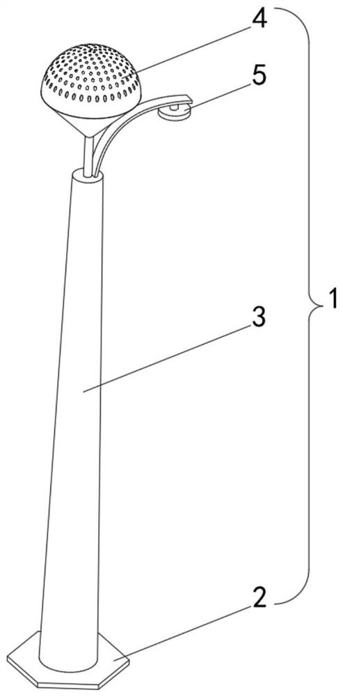
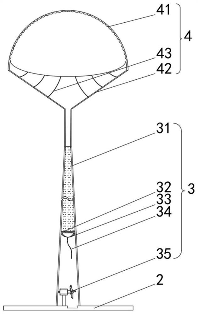
[0041] see Figure 1-2 , the present invention provides a technical solution: an environment-friendly street lamp, comprising an environment-friendly street lamp 1 composed of a base 2, a vertical rod 3, a water storage mechanism 4 and an energy-saving lamp 5, the top of the base 2 is fixedly connected to the bottom of the vertical rod 3 , the top of the vertical rod 3 communicates with the bottom of the water accumulation mechanism 4 through the water pipe, the top of the vertical rod 3 is fixedly connected with the outside of the energy-saving lamp 5 through the pole, the vertical rod 3 includes a vertical frame 31, and the inner walls of the vertical frame 31 are respectively A water control mechanism 32 and a drainage mechanism 33 are fixedly connected. The drainage mechanism 33 is located directly below the water control mechanism 32. The bottom of the drainage mechanism 33 is connected with a curved pipe 34. The top of the base 2 is fixedly connected with a hydroelectric ...

Embodiment 2

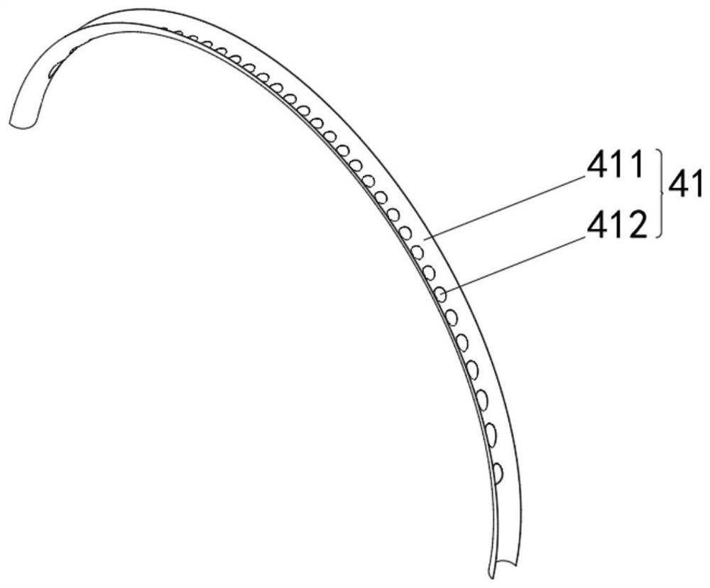
[0045] see Figure 1-5 On the basis of Embodiment 1, the present invention provides a technical solution: the outer filter plate 41 includes an outer slide plate 411, the bottom of the outer slide plate 411 is fixedly connected with the top of the inclined plate 42, and the inside of the outer slide plate 411 is provided with an outer slide hole 412.

[0046] The inner filter plate 43 includes an inner slide plate 431, the top of the inner slide plate 431 is fixedly connected to the inner side of the outer slide plate 411 through a support ring, the inner wall of the inner slide plate 431 is rotatably connected with a filter rotor 432, and the bottom of the inner slide plate 431 runs through the slant plate 42 and extends to The outside of the swash plate 42.

[0047] The filter rotor 432 includes a rotating shell 4321, the top of the inner wall of the rotating shell 4321 is rotationally connected with the inside of the inner slide plate 431 through the rotating pin 4322, the...

Embodiment 3

[0050] see Figure 1-8 , on the basis of Embodiment 1 and Embodiment 2, the present invention provides a technical solution: the water control mechanism 32 includes a water control plate 321, the outer side of the water control plate 321 is fixedly connected with the inner wall of the mullion 31, and the water control plate 321 The internal fixed connection flow limiting mechanism 6.

[0051] The current limiting mechanism 6 includes a magnetic frame 61, the outside of the magnetic frame 61 is fixedly connected to the inside of the water control plate 321, the inside of the magnetic frame 61 is slidably connected to a receiving rod 62, and the bottom of the receiving rod 62 is fixedly connected to a magnetic plate 63.

[0052] The bottom of the magnetic frame 61 is magnetically connected to the top of the magnetic plate 63 , the top of the receiving rod 62 is fixedly connected with a spring set 64 , and the bottom end of the spring set 64 is fixedly connected with the top of t...


PUM


Abstract

The invention discloses an environment-friendly street lamp which comprises a base, a vertical rod, a water accumulation mechanism and an energy-saving lamp, the top of the base is fixedly connected with the bottom of the vertical rod, the top of the vertical rod communicates with the bottom of the water accumulation mechanism through a water passing pipe, and the top of the vertical rod is fixedly connected with the outer side of the energy-saving lamp through a supporting rod; and the vertical rod comprises a vertical frame, the inner wall of the vertical frame is fixedly connected with a water control mechanism and a drainage mechanism, and the drainage mechanism is located under the water control mechanism. The invention relates to the technical field of environment protection. The environment-friendly street lamp solves the problems that in existing life, energy consumption is serious, the environment is polluted, most common street lamps are replaced by solar street lamps, but in some southern areas with much rainwater, the solar street lamps are prone to damage after being corroded by acid rain for a long time, a solar cell panel is corroded by rainwater, the risk of electric leakage exists, and unsafe factors exist.

Description

technical field [0001] The invention relates to the technical field of environmental protection technology, in particular to an environment-friendly street lamp. Background technique [0002] In people's production and living activities, on the one hand, we must study new methods and new processes, adopt new measures to save energy as much as possible, improve energy utilization, and reduce energy consumption; on the other hand, we must reduce and eliminate the discharge of energy pollutants , research, develop and utilize new non-polluting energy sources, and strive to achieve zero pollution and additional emissions; this is energy conservation and environmental protection. [0003] According to Chinese patent CN104566167A, the present invention discloses an energy-saving environment-friendly street lamp, which includes a base. A hydroelectric generator is provided, and an energy storage device is provided at the central position of the pole, and the hydroelectric generato...

Claims


Application Information

Patent Timeline
Patent Type & Authority Applications(China)
IPC IPC(8): F21S9/02F21S9/04F21V33/00F21V23/00B01D36/02F03B13/00F03B11/08F21W131/103
CPCY02B20/72Y02E10/20
Inventor 项磊
Owner 赵蓓蓓
Why Eureka
Try Eureka