Heat dissipation mechanism for new energy battery management

A technology for battery management and heat dissipation mechanism, which is applied to secondary batteries, battery pack components, and isolation of batteries from their environment.

Inactive Publication Date: 2021-04-16
林玉珍
View PDF10 Cites 6 Cited by
  • Summary
  • Abstract
  • Description
  • Claims
  • Application Information

AI Technical Summary

Problems solved by technology

[0005] In the above-mentioned patent, although the heat dissipation effect of the new energy battery can be realized, there are the following disadvantages: a water pump is required to realize the water cycle, and the work of the water pump needs to consume electric energy, resulting in insufficient energy saving, and the water in the air around the battery when water cooling is used It is easy to liquefy, which makes the battery easy to be affected by moisture; and the battery inside the protective box dissipates heat through the ventilation holes and air outlet holes, which makes it easy for the new energy vehicle to enter the protective box when wading, thus causing a short circuit of the battery; The air flow is easy to enter the dust, which makes the battery need to be cleaned and maintained regularly, which is more troublesome; and the heat dissipation form is single, resulting in poor heat dissipation effect of the new energy battery

Method used


Image

  • Heat dissipation mechanism for new energy battery management
  • Heat dissipation mechanism for new energy battery management
  • Heat dissipation mechanism for new energy battery management

Examples


Embodiment 1

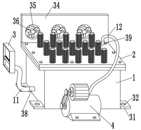
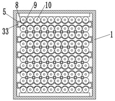
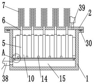
[0044] A dust removal device for a heat dissipation mechanism for new energy battery management, comprising a box body 1, the inside of the box body 1 is provided with uniformly distributed heat dissipation plates 5, the interior of the heat dissipation plate 5 is provided with a vacuum chamber 33, and the interior of the vacuum chamber 33 is in a vacuum state. With pure water, pure water is used as the refrigerant, and the battery body 10 is evenly distributed between two adjacent cooling plates 5, and the outer wall of one side of the cooling plate 5 is provided with evenly distributed left-shaped grooves 8, and the battery body 10 Compatible with the left-shaped groove 8, the outer wall of one side of the cooling plate 5 is provided with evenly distributed right-shaped grooves 9, and the battery body 10 is adapted to the right-shaped groove 9, and the top outer wall of the cooling plate 5 is welded with equidistant distribution. radiating pipe 6, the top of the radiating pip...


PUM


Abstract

The invention relates to the field of new energy vehicles, and aims to provide a heat dissipation mechanism for new energy battery management. The heat dissipation mechanism comprises a box body, uniformly distributed heat dissipation plates are arranged in the box body, vacuum cavities are formed in the heat dissipation plates, and uniformly distributed battery bodies are arranged between every two adjacent heat dissipation plates; uniformly distributed left grooves are formed in the outer wall of one side of the heat dissipation plate, the battery body is matched with the left grooves, uniformly distributed right grooves are formed in the outer wall of one side of the heat dissipation plate, the battery body is matched with the right grooves, and heat dissipation pipes distributed at equal intervals are welded to the outer wall of the top of the heat dissipation plate. Refrigerants are injected into the vacuum cavity of the heat dissipation plate, so that the refrigerants are heated to be evaporated and absorb heat, the evaporated refrigerants are cooled and liquefied in the heat dissipation pipe outside the box body, the heat dissipation plate can continuously cool the battery body in a reciprocating mode, electric energy does not need to be consumed, and the battery body is not prone to being affected with damp; therefore, an energy-saving effect during heat dissipation of battery management is achieved.

Description

technical field [0001] The invention relates to the field of new energy vehicles, in particular to a heat dissipation mechanism for new energy battery management. Background technique [0002] The new energy battery provides electric energy for the driving motor of the new energy vehicle, and the electric motor converts the electric energy of the power supply into mechanical energy. At present, the most widely used power source is lead-acid battery, but with the development of electric vehicle technology, lead-acid battery is gradually replaced by other batteries due to its low energy, slow charging speed and short life. The power sources under development mainly include sodium-sulfur batteries, nickel-cadmium batteries, lithium batteries, fuel cells, etc. The application of these new power sources has opened up broad prospects for the development of electric vehicles. [0003] Chinese Patent No. 201711154581.4 discloses a water-cooled heat dissipation structure for new ene...

Claims


Application Information

Patent Timeline
Patent Type & Authority Applications(China)
IPC IPC(8): H01M10/613H01M10/625H01M10/6551H01M10/6554H01M10/6556H01M10/6569H01M10/6563H01M10/653H01M50/249H01M50/24H01M50/213H01M10/42B08B1/02
CPCY02E60/10
Inventor 林玉珍
Owner 林玉珍
Why Eureka
Try Eureka