Supercharge Your Innovation With Domain-Expert AI Agents!

Ultrasonic cleaning equipment for optical lenses

A technology for optical lenses and cleaning equipment, applied in the field of optical lenses, can solve the problems of unfavorable lens cleaning, easy generation of air bubbles, incompleteness, etc., and achieve the effect of saving cleaning process, ensuring quality, and reducing friction

Active Publication Date: 2022-05-24
NANYANG KAIXIN PHOTOELECTRIC CO LTD
View PDF0 Cites 0 Cited by
  • Summary
  • Abstract
  • Description
  • Claims
  • Application Information

AI Technical Summary

Problems solved by technology

[0005] The purpose of the present invention is to provide a kind of ultrasonic cleaning equipment for optical lenses, to solve the problems mentioned above in the prior art that dust, oil stains, sweat stains, fingerprints and other dirt will be produced in the current optical lens manufacturing process in the prior art, which is unfavorable to the lens. The usual way of cleaning is to manually wipe with a dust-free cotton swab soaked in alcohol. However, this method is time-consuming and labor-intensive due to manual wiping one by one, and it is easy to cause secondary pollution to the surface of the optical lens.
The optical lens cleaning device in the prior art uses the method of spraying alcohol to clean, and this cleaning method will be mixed with dust and adsorbed on the mirror surface, resulting in incomplete and comprehensive cleaning, easy to generate air bubbles, and low efficiency

Method used


Image

  • Ultrasonic cleaning equipment for optical lenses
  • Ultrasonic cleaning equipment for optical lenses
  • Ultrasonic cleaning equipment for optical lenses

Examples


Embodiment Construction

[0028] The technical solutions in the embodiments of the present invention will be clearly and completely described below with reference to the accompanying drawings in the embodiments of the present invention. Obviously, the described embodiments are only a part of the embodiments of the present invention, but not all of the embodiments. The specific embodiments described herein are only used to explain the present invention, and are not intended to limit the present invention. Based on the embodiments of the present invention, all other embodiments obtained by those of ordinary skill in the art without creative efforts shall fall within the protection scope of the present invention.

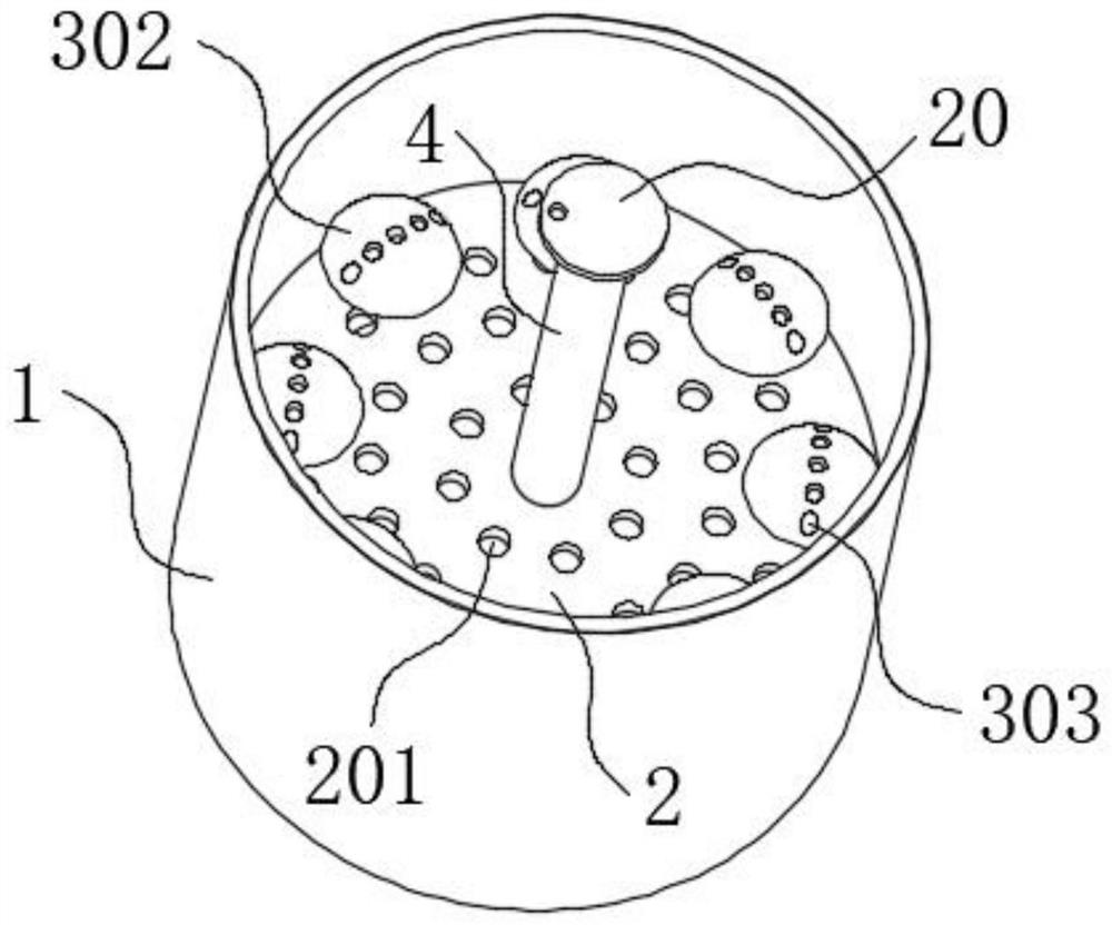
[0029] The present invention provides such as Figure 1-5 The shown ultrasonic cleaning equipment for optical lenses includes a cleaning cylinder 1, a tray 2 is slidably installed in the cleaning cylinder 1, and there are small holes 201 in a circular equidistant array in the tray 2, and the sm...


PUM


Abstract

The invention discloses an ultrasonic cleaning device for optical lenses, which comprises a cleaning cylinder, a tray is slidably installed in the cleaning cylinder, small holes are arranged in an equidistant annular array in the tray, and optical holes are arranged in an equidistant annular array on the upper surface of the tray. A lens support assembly, a hollow tube is installed in the middle of the tray, the surface of the hollow tube is screwed with a pressure plate, the lower surface of the pressure plate is equidistant from the circular array with a compression assembly, and the top of the cleaning cylinder is provided with a bucket cover A motor is fixedly installed on the top of the barrel cover, one end of the hollow tube is installed through the barrel cover and extends to the outside of the cleaning cylinder, a transmission assembly is arranged between the top end of the hollow tube and the output shaft end of the motor, the The optical lens support assembly includes a column, and a top block is fixedly installed on the top of the column, and through holes are opened in the top block, and the pressing assembly includes a pressing block, which ensures the quality of the optical lens after cleaning.

Description

technical field [0001] The invention belongs to the technical field of optical lenses, in particular to an ultrasonic cleaning device for optical lenses. Background technique [0002] The optical glass lens is made of high-purity silicon, boron, sodium, potassium, zinc, lead, magnesium, calcium, barium and other oxides mixed according to a specific formula, melted at high temperature in a platinum crucible, stirred evenly with ultrasonic waves to remove air bubbles; Cool down slowly for a long time to avoid internal stress on the glass block. The cooled glass block is heated and forged to form an optical lens blank, and then polished to form an optical lens. [0003] In the current optical lens manufacturing process, dust, oil, sweat, fingerprints and other dirt will be generated, which is not conducive to the cleaning of the lens. The usual method is to manually wipe with a dust-free cotton swab soaked in alcohol. However, this method is due to Manually wiping one by one ...

Claims


Application Information

Patent Timeline
Patent Type & Authority Patents(China)
IPC IPC(8): B08B3/12B08B13/00F26B21/00
Inventor 郑为学
Owner NANYANG KAIXIN PHOTOELECTRIC CO LTD
Features
  • R&D
  • Intellectual Property
  • Life Sciences
  • Materials
  • Tech Scout
  • Unparalleled Data Quality
  • Higher Quality Content
  • 60% Fewer Hallucinations
Learn More