
Silicon wafer etching method

A silicon wafer and etching technology, which is applied in manufacturing tools, laser welding equipment, semiconductor devices, etc., can solve the problems of time-consuming, labor-intensive, reduced processing efficiency, and large amount of operation.

Active Publication Date: 2021-04-20
内蒙古兴固科技有限公司
View PDF28 Cites 2 Cited by
  • Summary
  • Abstract
  • Description
  • Claims
  • Application Information

AI Technical Summary

Problems solved by technology

[0003] The processing of silicon wafers includes steps such as doping, melting, cutting, grinding, etching, and cleaning. During etching, silicon wafers need to be loaded and unloaded manually, which requires a large amount of operation, time-consuming and laborious, and additional silicon The positioning of the wafer is fixed, therefore, reducing the processing efficiency

Method used


Image

  • Silicon wafer etching method
  • Silicon wafer etching method
  • Silicon wafer etching method

Examples


Embodiment Construction

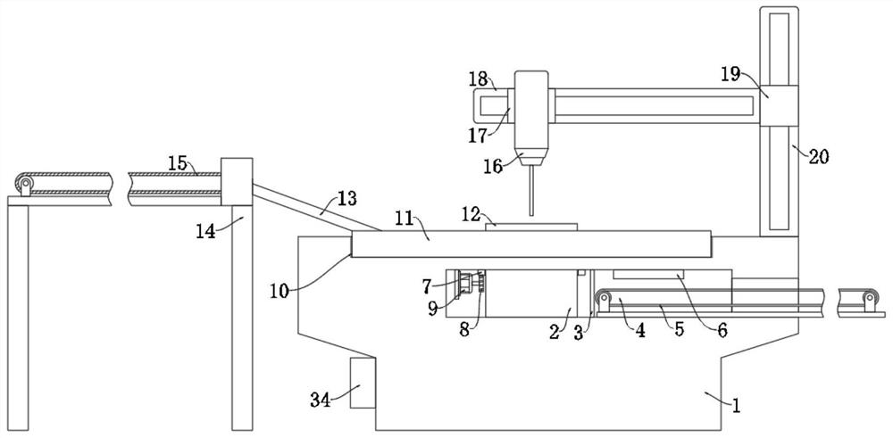
[0027] The following will clearly and completely describe the technical solutions in the embodiments of the present invention with reference to the accompanying drawings in the embodiments of the present invention. Obviously, the described embodiments are only some, not all, embodiments of the present invention.

[0028] In describing the present invention, it should be understood that the terms "upper", "lower", "front", "rear", "left", "right", "top", "bottom", "inner", " The orientation or positional relationship indicated by "outside", etc. is based on the orientation or positional relationship shown in the drawings, and is only for the convenience of describing the present invention and simplifying the description, rather than indicating or implying that the referred device or element must have a specific orientation, so as to Specific orientation configurations and operations, therefore, are not to be construed as limitations on the invention.

[0029] refer to Figure ...


PUM


Abstract

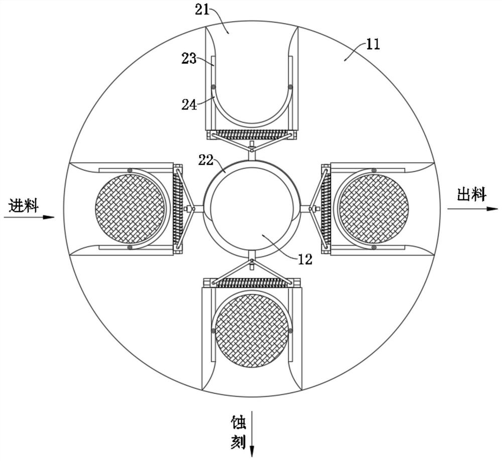
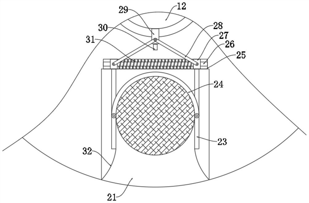
The invention discloses a silicon wafer etching method, which comprises the following steps: S1, a silicon wafer to be processed is conveyed to a feeding groove of an etching device through a feeding conveying belt, and the silicon wafer is guided into a placing groove, so that the silicon wafer slides into a part between two clamping blocks; S2, a stepping motor is started, a gear is driven to rotate, a gear ring is driven to rotate, then a rotating disc is driven to rotate, the fed silicon wafer rotates away from a feeding side along with rotation of the rotating disc, at the moment, an abutting block rotates away from a flange, the flange does not generate abutting supporting force on the abutting block any more, then a tension spring pulls two movable blocks to move close to each other, and the two clamping blocks are driven to get close to clamp and fix the silicon wafer; and S3, a vertical electric guide rail and a transverse electric guide rail are started to drive a laser etching machine head to operate to complete etching. Automatic feeding and discharging of the silicon wafer can be achieved, the feeding and discharging efficiency is improved, stable feeding, etching and discharging of the silicon wafer are realized, the working intensity of manual feeding is reduced, the feeding and fixing processes of the silicon wafer are integrated, and time and labor are saved.

Description

technical field [0001] The invention relates to the technical field of silicon wafer production and processing, in particular to a silicon wafer etching method. Background technique [0002] Silicon wafers, also known as wafers, are processed from silicon ingots. Millions of transistors can be etched on silicon wafers through special processes, and are widely used in the manufacture of integrated circuits. Silicon carbide wafers The main application areas are LED solid-state lighting and high-frequency devices. It has irreplaceable advantages in the field of electronic applications and extreme environment applications such as aerospace, military industry, and nuclear energy. [0003] The processing of silicon wafers includes steps such as doping, melting, cutting, grinding, etching, and cleaning. During etching, silicon wafers need to be loaded and unloaded manually, which requires a large amount of operation, time-consuming and laborious, and additional silicon The positi...

Claims


Application Information

Patent Timeline
Patent Type & Authority Applications(China)
IPC IPC(8): B23K26/362B23K26/08B23K26/70B23K101/40
CPCY02P70/50
Inventor 陶金
Owner 内蒙古兴固科技有限公司
Learn More