[0062] The following examples can enable those skilled in the art to understand the present invention more comprehensively, but the present invention is not limited to the scope of the described examples.
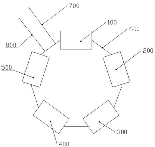
[0063] like Figure 2-Figure 13 The brake bottom plate processing production line shown in the figure includes a car plane unit, a milling plane unit, a mounting hole drilling unit, an assembly hole boring unit, and a dust-proof hole drilling unit distributed sequentially in a ring shape. The transition conveyor belt 600 is connected to form an endless cycle, and a feed conveyor belt 700 and a discharge conveyor belt 800 are also provided at the side end of the transition conveyor belt 600 for connecting the dust-proof hole drilling unit and the car plane unit, The feeding conveyor belt 700 is located on the side close to the car plane unit, and the discharging conveyor belt 800 is located on the side close to the dust-proof hole drilling unit.
[0064] Car plane unit comprises a lathe frame 100, and a car plane platform 201 is installed in lathe frame 100, as image 3 It can be seen from the schematic diagram that the vehicle plane platform 201 is a circular plate structure, and vehicles are arranged above the vehicle plane platform 201 .
[0065] The first support assembly is installed on the car flat platform 201, and the first support assembly includes three support seats that are distributed on the upper end surface of the car flat platform 201 in a character shape, which are respectively the first support seat, the second support seat and the third support seat. Support base.
[0066] The first support seat includes a first fixed seat 202 fixed on the car flat platform 201, the first fixed seat 202 is in the shape of a cuboid, and the outer surface of the first fixed seat 202 is an arc consistent with the circumferential surface of the car flat platform 201 On the top of the first fixing seat 202, a first compression cylinder 203 is also installed, and the cylinder body of the first compression cylinder 203 is locked and fixed between the bolt and the first fixing seat 202. In the first compression cylinder The top end of the piston rod of 203 is connected with a first compression block extending toward the center of the vehicle plane platform, and the side of the first fixing seat 202 near the center of the vehicle plane platform 201 extends out of the first compression cylinder 203, and the second A section of a fixing base 202 protruding from the first compression cylinder 203 is a first supporting section 204 .
[0067] Both sides of the bottom end of the first support seat also have a first flanging structure 205 that is turned outwards horizontally, and the first flanging structure 205 is screwed with the car plane platform 201 by bolts, and simultaneously the first flanging structure 205 There is a through hole for allowing bolts to pass through, and there is an internal thread blind hole threaded with bolts on the vehicle plane platform 201 . For the bottom end of the first support seat, the first flange structure 205 is used to fix the connection mode with the car plane platform 201 by screwing, thereby realizing the quick connection between the first support seat and the car plane platform 201, and also facilitating the first support seat disassembly, so that the first support seats of different heights can be selected according to the main body of the bottom plate of different sizes, and the versatility is stronger.
[0068] The second support seat includes a second fixed seat 206 fixed on the car flat platform 201, the second fixed seat 206 is cuboid, and the outer surface of the second fixed seat 206 is consistent with the circumferential surface of the car flat platform 201 The arc surface is also equipped with a second compression cylinder 207 on the top of the second fixed seat 206, and is fixed by bolt locking between the second compression cylinder 207 cylinder block and the second fixed seat 206, and the second compression cylinder The top of the piston rod of 207 is connected with a second compression block extending toward the center of the vehicle plane platform 201, and the side of the second fixed seat 206 near the center of the vehicle plane platform 201 extends out of the second compression cylinder, and the first A section of the second fixing seat 206 protruding from the second pressing cylinder 207 is the second supporting section.
[0069] Both sides of the bottom end of the second support base also have a second flanging structure 208 that is turned outward horizontally, and the second flanging structure 208 is screwed with the car plane platform 201 by bolts. There are through holes for bolts to pass through, and internal thread blind holes matched with bolts are arranged on the car plane platform 201 . For the bottom end of the second support seat, the second flange structure 208 is used to fix the connection mode with the car plane platform 201 by screwing, thereby realizing the quick connection between the second support seat and the car plane platform 201, and also facilitating the second support seat. The disassembly, so that the second support seat of different heights can be selected according to the main body of the bottom plate of different sizes, and the versatility is stronger.
[0070]The 3rd support seat comprises a 3rd fixed seat fixed on the car plane platform 201, and the 3rd fixed seat is made up of two fixed supports 209 that distribute in half, and the fixed support 209 is fan shape, and two fixed supports 209 are combined to form a semicircular shape. This design is also for the convenience of processing the fixed bracket 209. It only needs to take a semicircular plate and cut it from the middle to form two fixed supports 209. Between the two fixed supports 209 There is a gap, and a third compression cylinder 210 is installed in the gap between the two fixed supports 209. Both sides of the cylinder body of the third compression cylinder 210 are fixed with the two fixed supports 209 by bolts. The top end of the piston rod of the compression cylinder 210 is connected with a third compression block extending toward the center of the vehicle plane platform 201 , and the cylinder body of the third compression cylinder 210 is a third support section.
[0071] The plane milling unit includes a milling machine frame 200, and a milling plane platform 1 is installed in the milling machine frame 200, such as Figure 4-Figure 6 It can be seen from the schematic diagram shown that a milling tool is arranged above the plane milling platform 1 .
[0072] A support base is installed on the plane milling platform 1, and the support base is composed of a first support section 2 and a second support section 3 distributed up and down, wherein the second support section 3 is fixed on the middle position of the upper end surface of the plane milling platform 1 , the first support section 2 and the second support section 3 are both cylindrical, and the diameter of the first support section 2 is greater than the diameter of the second support section 3, and the height of the first support section 2 is less than the height of the second support section 3, Thus, the entire supporting base is in a T-shape.
[0073] A second compression assembly is also installed on the milling plane platform 1, and the second compression assembly includes a second compression plate 4, a second compression block 5, a second compression bolt 6, and a second compression nut, wherein, The second hold-down bolt 6 passes through the support base and the milling plane platform 1 is threaded and fixed, and at the same time, at the center of the support base, there is a first through hole 61 that penetrates the support base up and down and allows the second hold-down bolt 6 to pass through. The pressing plate 4 is located above the first support section 2 of the supporting base, and there is a gap for the bottom plate of the brake between the second pressing plate 4 and the supporting base, and there is a middle position of the second pressing plate 4 The through hole that allows the second compression bolt 6 to pass through, the second compression block 5 is located above the second compression plate 4, and there is a second compression block 5 on the second compression block 5 that runs through the entire second compression block 5 up and down. Two through holes, the second compression nut is located above the second compression block 5, and is threadedly matched with the second compression bolt 6, so as to realize the limit and fixation of the upper end of the second compression block 5.
[0074] The second compression block 5 includes a second compression block main body 52 and three second compression block splits 51 distributed on the outside of the second compression block main body 52, and the second compression block splits 51 and the first compression block The two compression block main bodies 52 are connected in a star-shaped manner, and the connection between the second compression block body 51 and the second compression block main body 52 is arc-shaped transition connection.
[0075] The second through hole is a U-shaped hole, and one side of the second through hole extends to the outside of the second pressing block 5 to form a U-shaped opening. For the design of the second through hole, the design of the U-shaped opening is adopted, so that when the second compression block 5 is assembled, it can be assembled directly from the side end of the second compression bolt 6, which is very convenient.
[0076] The mounting hole drilling unit includes a drilling machine frame 300, and a first drilling base plate 301 is installed in the drilling machine frame 300, such as Figure 7-Figure 9 As shown, a drilling tool is arranged above the first drilling floor 301 .
[0077] A third support assembly is installed on the first drilling floor 301. The third support assembly includes a third support column installed on the first drilling floor 301. The third support column is stepped and distributed sequentially from top to bottom. The first stepped section 302, the second stepped section 303, and the third stepped section 304 are composed in sequence, the first stepped section 302, the second stepped section 303, and the third stepped section 30 are all cylindrical, and the first stepped section 302, The diameters of the second stepped section 303 and the third stepped section 304 decrease successively, and the heights of the second stepped section 303, the first stepped section 302, and the third stepped section 304 decrease successively, and the first stepped section 302, the second stepped section 303 and the third step section 304 are all sleeved on the outside of the third hold-down bolt 305, and there is a third hold-down bolt 305 in the centers of the first step section 302, the second step section 303 and the third step section 304. Through the internal threaded through hole, the third step section 304, the second step section 303, and the first step section 302 are therefore set on the third hold-down bolt 305, and are screwed with the third hold-down bolt 305. The outer side of the top end of the first stepped section 302 also has an annular groove for fitting into the central hole of the main body of the bottom plate. For the third support column, the combined structure of the first step section 302, the second step section 303, and the third step section 304 can be selected and installed according to the processing requirements. The number of sections 304, so as to realize the adjustment of the overall height of the third support column, and for the first step section 302, the second step section 303, the third step section 304 and the third hold-down bolt 305 are fixed by threads, then It is to facilitate the installation and disassembly of the first step section 302, the second step section 303, and the third step section 304, and save assembly time.
[0078] On the first drilling floor 301, a third pressing assembly is also provided, the third pressing assembly includes a third pressing bolt 305 vertically fixed on the first drilling floor 301, the third pressing bolt 305 directly It is welded and fixed with the first drilling bottom plate 301, and after the third compression bolt 305 passes through the entire third support column from bottom to top, the upper end of the third compression bolt 305 extends out of the first stepped section of the third support column After 302, a third compression block 306 is also set on the outside of the third compression bolt 305 above the third support column. The length of the third compression block 306 is longer than the diameter of the central hole of the bottom plate main body. The middle position of the compression block 306 has a through hole for the third compression bolt 305 to pass through, and the third compression block 306 is locked and fixed by a third compression nut sleeved on the third compression bolt 305 .
[0079] Assembly hole boring unit comprises a boring machine frame 400, and a second boring platform 401 is installed in the boring machine frame 400, as Figure 10-Figure 12 As shown, a boring tool is provided above the second boring platform 401 .
[0080] A fourth support assembly is installed on the second boring platform 401, the fourth support assembly includes an assembly hole support column 402 vertically fixed on the upper end surface of the second boring platform 401, an installation hole support column 403, the assembly hole support The column 402 and the mounting hole support column 403 are both cylindrical, and the diameter of the mounting hole support column 403 is larger than the diameter of the assembly hole support column 402. There are two mounting hole support columns 403, which are respectively arranged on the second boring platform 401. On both sides of the long axis direction, there are also annular grooves for fitting the mounting holes of the main body of the bottom plate on the outer wall of the top of the mounting hole support column 403. There are several assembly hole support columns 402, which are distributed in two groups in two installations. Between the hole support columns 403, each assembly hole support column group is composed of several assembly hole support columns 402 distributed along the long axis direction of the second boring platform 401, and each assembly hole support column group in the same group The hole support columns 402 are distributed in an arc shape, and the positions of the assembly hole support columns 402 correspond to the respective assembly holes on the bottom plate main body.
[0081] A fourth pressing assembly is also installed on the second boring platform 401. The fourth pressing assembly includes a fourth pressing bolt 404 vertically fixed on the upper end surface of the second boring platform 401. The fourth pressing assembly The lower end of the bolt 404 is threadedly fixed between the second boring platform 401, and at the same time, on the upper end surface of the second boring platform 401, there is also a threaded blind hole threaded with the fourth pressing bolt 404. On the bolt 404, the fourth compression block 405, the fourth cushion block 406, and the fourth sealing plate 407 are sequentially set from top to bottom. There is a through hole for the fourth compression bolt 404 to pass through. The top end of the fourth compression block 405 is locked by the fourth lock nut. The diameter of the fourth sealing plate 407 is larger than the diameter of the central hole of the bottom plate main body. On the outer wall of the lower end surface of the sealing plate 407, there is also an annular groove for fitting the central hole of the main body of the bottom plate. During processing, waste chips generated during processing fall into the center hole of the main body of the bottom plate.
[0082] There is also an opening at the side end of the fourth pressing block 405 that communicates with the through hole on the fourth pressing block 405, so that the entire fourth pressing block 405 is U-shaped. For the design of the opening of the side end of the fourth compression block 405, so that the fourth compression block 405 can be inserted directly from the side end of the fourth compression bolt 404 during assembly, without the need to go from above the fourth compression bolt 404 Slips on for easy assembly.
[0083] The fourth spacer 406 is in the shape of a circular platform, and the end surface of the fourth spacer 406 with a large diameter is in contact with the fourth sealing plate 407, and the end surface of the fourth spacer 406 with a small diameter is in contact with the fourth pressing block. 405 fit together. For the fourth cushion block 406 adopting the design of circular frustum, it is to play a transitional effect on the fourth pressing block 405 and the fourth sealing plate 407, because the fourth sealing plate 407 is used to carry out the central hole of the base plate main body Sealed, so the diameter of the fourth sealing plate 407 will be relatively large, and for the sake of weight reduction, the fourth sealing plate 407 will be made thinner, and the fourth pressing block 405 is to play the role of locking and fixing , so the diameter of the fourth pressing block 405 can be designed very small, and the thickness of the fourth pressing block 405 will be relatively thick. Based on this situation, if the fourth pressing block 405 is directly pressed against the fourth When the sealing plate 407 is on, it is easy to press and bend the fourth sealing plate 407 and other bad phenomena.
[0084] The dust-proof hole drilling unit comprises a drilling machine frame 500, and a 3rd drilling platform is installed in the drilling machine frame 500, as Figure 13 As shown, a drilling tool is arranged above the third drilling platform.
[0085] The third drilling platform is formed by joint connection of a vertical section 501 and a horizontal section 502 , and the third drilling platform is in the shape of a flat T as a whole.
[0086] A pair of stiffeners 503 is also connected to the bottom end surface of the horizontal section 502 of the third drilling platform, and one side of the ribs 503 is fixed to the vertical section 501 of the third drilling platform. The reinforcing rib 503 provided between the horizontal section 502 and the vertical section 501 is to ensure the stability of the connection between the horizontal section 502 and the vertical section 501, thereby ensuring the structural strength of the entire third drilling platform.
[0087] A lightening hole 504 is also provided on the horizontal section 502 of the third drilling platform, and the lightening hole 504 is a rectangular through hole. For the design of the lightening hole 504 on the third drilling platform, the weight of the horizontal section 502 is reduced on the basis of ensuring the structural strength of the horizontal section 502 .
[0088] The fifth support assembly is installed on the horizontal section 502 of the third drilling platform, the fifth support assembly includes a pair of fifth support columns 505 installed on the upper end surface of the horizontal section 501 of the third drilling platform, and two The fifth support columns 505 are all located on one side of the vertical section 501 close to the third drilling platform, and the two fifth support columns 505 are respectively corresponding to the mounting holes of the two bottom plate main bodies. There is also an annular positioning groove on the peripheral outer wall to accommodate the mounting hole of the main body of the bottom plate to be embedded.
[0089] The fifth pressing assembly is also installed on the horizontal section 502 of the third drilling platform, and the fifth pressing assembly includes a fifth pressing block 506 horizontally arranged above the horizontal section 502 of the third drilling platform. The compression block 506 is fixed on the horizontal section 502 of the third drilling platform through the cooperation of two sets of fifth compression bolts 507 and the fifth lock nut. The through hole that tightening bolt 507 passes, the 5th hold down bolt 507 passes through the through hole on the 5th hold down block 506 and is threaded with the horizontal section 502 of the 3rd drilling platform, simultaneously at the level of the 3rd drilling platform The upper end surface of the segment 502 also has a threaded blind hole matched with the fifth pressing bolt 507 .
[0090]Working principle: Firstly, the main body of the bottom plate to be processed is transported into the whole system through the feeding conveyor belt 700, and the main body of the bottom plate is transported from the feeding conveyor belt 700 to the transition conveyor belt 600. In this process, the bottom plate on the feeding conveyor belt 700 is manually The main body is placed on the transition conveyor belt 600, and then transported to the car plane unit by the transition conveyor belt 600;
[0091] When processing at the car plane unit, the car plane platform 201 is fixed on the lathe frame 100, and the main body of the base plate to be processed is respectively supported on the first support section 204, the second support section, and the third support section, and passed The first support section 204, the second support section, and the third support section cooperate together to realize the rapid positioning of the main body of the bottom plate, and then, the first compression cylinder 203, the second compression cylinder 207, and the third compression cylinder 210 act together , respectively drive the first compression block, the second compression block, and the third compression block downward to realize the three-point fixation of the main body of the bottom plate. and chamfering.
[0092] The processed brake bottom plate is manually taken out and placed on the transition conveyor belt 600, and then transported to the milling plane unit by the transition conveyor belt 600 for processing. First, the milling plane platform 1 is fixed on the milling machine frame 200, and then , place the brake base plate to be processed on the upper end surface of the first support section 2, and after placing it, place the second pressing plate 4 on the central hole in the middle of the brake base plate, and the second pressing plate 4 is just right Fit with the center hole of the brake bottom plate, then place the second compression block 5 on the upper end surface of the second compression plate 4, and pass the second through hole of the second compression block 5 through the second Compress the bolt 6, and finally tighten the second compression nut, so that the second compression nut is pressed against the upper end surface of the second compression block 5, thereby completing the fixing of the brake bottom plate, and finally using the cutter on the milling machine to mill the brake The plane of the base plate.
[0093] The processed brake bottom plate is manually taken out and placed on the transition conveyor belt 600, and then transported to the installation hole drilling unit by the transition conveyor belt 600 for processing, and the first drilling bottom plate 301 is fixed on the corresponding drilling machine frame 300, then place the main body of the bottom plate to be processed on the third support column, align the central hole of the main body of the bottom plate with the annular groove on the first step section 302 of the third support column, fit and position, and then Set the third compression block 306 on the third compression bolt 305, and then use the third compression nut to lock above the third compression block 306, so that the third compression block 306 realizes the upper end surface of the main body of the bottom plate. Then use the drilling tool on the drilling machine to process the mounting holes on both sides of the main body of the bottom plate, and then remove the first drilling bottom plate 301 from the drilling machine and fix it on another drilling machine at a certain angle. The inclination angle of the first drilling bottom plate 301 corresponds to the inclination angle of the nozzle hole of the bottom plate main body, so that the required nozzle hole is in a vertical state, and then the vertical hole is drilled with a drilling tool, which is the required Slanted nozzle holes.
[0094] The processed brake bottom plate is manually taken out and placed on the transition conveyor belt 600, and then transported to the assembly hole boring unit by the transition conveyor belt 600 for processing, and the second boring platform 401 is fixed on the corresponding boring machine frame 400, then place the main body of the base plate to be processed on the mounting hole supporting column 402 and the mounting hole supporting column 403 on the second boring platform 401, and respectively set the two mounting holes on both sides of the base plate main body in the mounting hole The position of the annular groove on the support column 403, so as to realize the fast positioning of the main body of the bottom plate, and then the fourth sealing plate 407 is set on the fourth pressing bolt 404, and the annular groove on the fourth sealing plate 407 and The center hole of the main body of the bottom plate is aligned and fitted, and then the fourth cushion block 406 and the fourth pressing block 405 are sequentially fitted on the fourth sealing plate 407, and finally the fourth locking bolt is threaded on the fourth pressing bolt 404. The nut realizes the locking of the fourth pressing block 405 to compress the main body of the base plate. Finally, the boring tool on the boring machine is used to bore the main body of the base plate to process each assembly hole on the main body of the base plate.
[0095] The processed brake bottom plate is manually taken out and placed on the transition conveyor belt 600, and then transported to the dust-proof hole drilling unit by the transition conveyor belt 600 for processing, and the third drilling platform is installed on the corresponding drilling machine frame 500, then place the two bottom plate bodies with processing on both sides of the horizontal section 502 of the third drilling platform respectively, and align the mounting holes of the bottom plate bodies with the annular grooves on the fifth support column 505 combined positioning, the other side of the two bottom plate bodies is compressed by the same fifth pressing block 506, and the fifth pressing block 506 is pressed on the upper end surface of another mounting hole of the bottom plate main body, and after pressing, use The fifth locking nut is tightened and fixed, and finally, the dust-proof hole of the main body of the bottom plate is processed by using the corresponding drilling tool on the drilling machine.
[0096] Finally, all the processed brake bottom plates are manually taken out, placed on the transition conveyor belt 600, and then transported by the transition conveyor belt 600, and when transported to the discharge conveyor belt 800, the braking point is manually moved from the transition The conveyor belt 600 is transported and placed on the discharge conveyor belt 800, and is sent out by the discharge conveyor belt 800 to complete the entire processing.
[0097] The production line in the present invention adopts the cooperation of the car plane unit, the milling plane unit, the mounting hole drilling unit, the assembly hole boring unit, and the dustproof hole drilling unit of the ring shape distribution, and cooperates with the design of the transition conveyor belt, so that it can The main body of the bottom plate is processed in sequence to avoid missing processing and ensure the completion of processing. Moreover, this arrangement method is used to arrange each processing machine tool reasonably, effectively reducing the occupied area and improving the utilization rate of the plant. .
[0098] Those skilled in the industry should understand that the present invention is not limited by the above-mentioned embodiments. What are described in the above-mentioned embodiments and the description only illustrate the principle of the present invention. Without departing from the spirit and scope of the present invention, the present invention will also have Variations and improvements all fall within the scope of the claimed invention. The protection scope of the present invention is defined by the appended claims and their equivalents.