Storage device for blood routine examination waste liquid

A blood routine detection and storage device technology, applied in the field of medical waste treatment, can solve the problems of suspended solids generation, separation, environmental pollution, etc., and achieve the effect of preventing aging

Pending Publication Date: 2021-04-20
PEOPLES HOSPITAL OF ZHENGZHOU
8 Cites 0 Cited by

AI-Extracted Technical Summary

Problems solved by technology

[0002] When testing the drawn blood, it is necessary to add different testing fluids according to different testing items. Therefore, the waste fluid of blood routine testing contains bacteria, viruses, organic matter and chemical agents, and the testing waste fluid needs to be pretreated. Aerobic bacteria decompose organic matter, ozone sterilization and chemical treatment before it can be discharged into the storage device. The organic matter in the waste liquid is decomposed by aerobic bacteria to produce carbon dioxide and ammonia gas, and ammonia gas is very soluble in water. Carbon dioxide and ammonia gas Dissolving in waste liquid will change its pH value, and stirring and temperature changes in the storage device will easily...

Method used

By adopting above-mentioned technical scheme: by the heating coil (30) that is provided with, carbon dioxide and ammonia in the waste liquid can be discharged quickly, convenient to adjust the pH value in the storage device next, open the heating coil (30) to improve waste The temperature of the liquid can quickly discharge the carbon dioxide and ammonia in the waste liquid, avoiding the change of pH value in the waste liquid due to gas factors, and the generated carbon dioxide and ammonia are discharged through the first exhaust port (16), and the flocculant The hydrolysis reaction is an endothermic reaction. The heating coil (30) works to facilitate the hydrolysis of the flocculant and the formation of flocs. At the same time, the control mechanism (17) can control the power of the heating coil (30) to avoid the The temperature of the solution exceeds 90 degrees Celsius to prevent the aging of the flocculant...

Abstract

The invention discloses a blood routine examination waste liquid storage device, and the device comprises a storage box and a pretreatment mechanism; a laser emitter and a laser receiver are fixedly installed on the left side and the right side of the storage box respectively, and laser emitted by the laser emitter can irradiate a corresponding receiving area on the laser receiver through the interior of the storage box; four PH value measuring probes are uniformly distributed and fixed in the storage box, a heating coil is mounted in a box body at the lower half part of the storage box, a precipitate discharge port is formed in the bottom of the storage box, and a fixed block is fixedly connected to the outer wall of the precipitate discharge port. According to the storage device for the blood routine examination waste liquid, carbon dioxide and ammonia gas in the waste liquid can be rapidly discharged through the heating coil, the PH value in the storage device can be conveniently adjusted subsequently, the heating coil is started to increase the temperature of the waste liquid, the carbon dioxide and the ammonia gas in the waste liquid can be rapidly discharged, and the change of the pH value in the waste liquid caused by gas factors is avoided.

Application Domain

Technology Topic

Image

  • Storage device for blood routine examination waste liquid
  • Storage device for blood routine examination waste liquid
  • Storage device for blood routine examination waste liquid

Examples

  • Experimental program(2)

Example Embodiment

[0029] Example 1
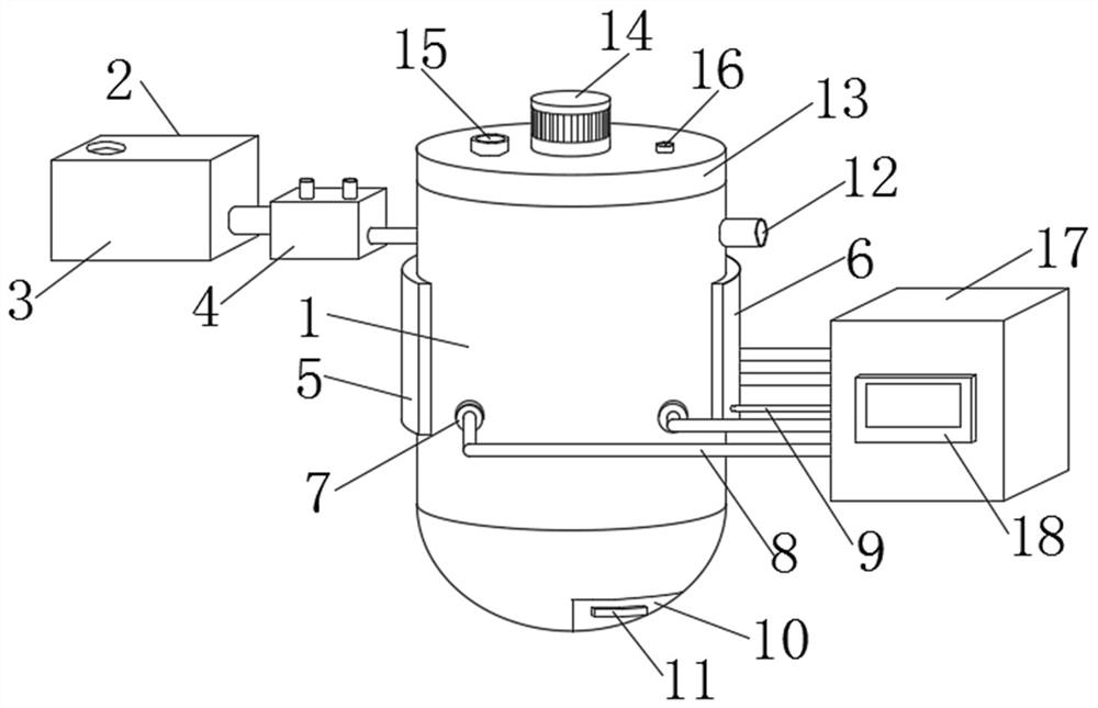
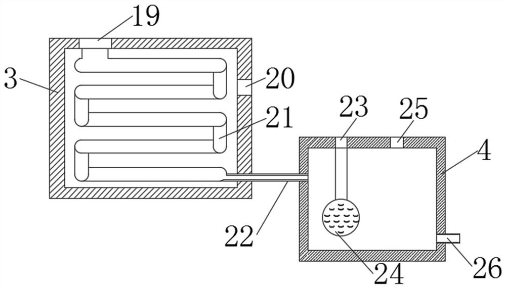
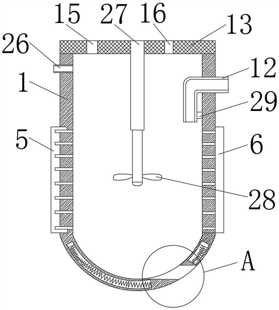
[0030] like Figure 1-6 As shown, a storage device for blood routine testing waste liquid includes a storage box (1) and a pretreatment mechanism (2). The left and right sides of the storage box (1) are respectively fixed with a laser transmitter (5) and a laser receiver. laser emitter (6), the laser emitted by the laser transmitter (5) can pass through the interior of the storage box (1) to irradiate the corresponding receiving area on the laser receiver (6), and the interior of the storage box (1) is evenly distributed and fixed with four A pH value measuring probe (7), a heating coil (30) is installed in the lower half of the storage box (1), the bottom of the storage box (1) is provided with a sediment discharge port (10), and the sediment discharge port ( The outer wall of 10) is fixedly connected with a fixed block (11), the top of the storage box (1) is equipped with a detachable sealing cover (13), the fixed block (11) can assist the sediment discharge port (10) to open and can be easily fixed The storage box (1), the bottom of the storage box (1) is arc-shaped.
[0031] The inside of the sealing cover (13) is provided with a feeding port (15) and a first exhaust port (16), and the feeding port (15) and the first exhaust port (16) are respectively located on the left and right sides of the motor (14), sealed The lower end of the shaft center of the cover (13) is equipped with a telescopic rod (27), and the outer wall of the lower end of the telescopic rod (27) is equipped with some angle adjustment blocks (31), and the angle adjustment block (31) is far away from the telescopic rod (27). ) is fixedly installed with a blade (28), the radian of the blade (28) matches the radian of the bottom of the storage box (1), the top of the sealing cover (13) is fixed with a motor (14), and the feeding port (15) It is used to add flocculant, and the first exhaust port (16) is used to discharge carbon dioxide and ammonia due to heating.
[0032] The pretreatment mechanism (2) includes a first pipeline (22), a second pipeline (26), a first treatment box (3) and a second treatment box (4), and the two ends of the first pipeline (22) run through the first The treatment box (3) and the second treatment box (4), and the two ends of the second pipeline (26) respectively run through the second treatment box (4) and the storage box (1).
[0033] The interior of the first treatment box (3) is equipped with a biological decomposition pipe (21), the top of the first treatment box (3) is provided with a waste input port (19), and one side of the first treatment box (3) is provided with a second The exhaust port (20), the gas produced by the aerobic bacteria in the biological decomposition pipe (21) decomposing organic matter is discharged through the second exhaust port (20), and the top of the second treatment box (4) is respectively provided with ozone ports (23 ) and the chemical input port (25), the inside of the second treatment box (4) is provided with an ozone ball (24), the inlet end of the ozone ball (24) is connected with the ozone port (23), and the ozone ball (24) A number of pores are provided on the wall of the ball to help the ozone fully contact with the waste liquid in the second treatment box (4) to improve the killing efficiency of bacteria and viruses.
[0034] The signal output end of the laser receiver (6) is fixedly connected with the second signal line (9), and the signal output ends of the four pH value measuring probes (7) are all fixedly connected with the first signal line (8), and the first signal line (8) and the end of the second signal line (9) far away from the storage box (1) is connected with a control mechanism (17), and the front of the control mechanism (17) is fixed with a touch control panel (18), and the touch control panel (18 ) can display the pH value measured by the four pH value measuring probes (7), the temperature of the waste liquid in the storage box (1) and whether the laser light received by the laser receiver (6) is scattered.
[0035] By adopting the above technical solution: through the heating coil (30), the carbon dioxide and ammonia in the waste liquid can be quickly discharged, which is convenient for adjusting the pH value in the storage device, and turning on the heating coil (30) to increase the temperature of the waste liquid , can quickly discharge the carbon dioxide and ammonia in the waste liquid, avoiding the change of pH value in the waste liquid due to gas factors, the generated carbon dioxide and ammonia are discharged through the first exhaust port (16), and the hydrolysis reaction of the flocculant It is an endothermic reaction. The heating coil (30) works to facilitate the hydrolysis of the flocculant and the formation of flocs. At the same time, the control mechanism (17) can control the power of the heating coil (30) to avoid the temperature of the solution in the storage tank (1). Over 90 degrees Celsius to prevent the aging of the flocculant.

Example Embodiment

[0036] Example 2
[0037] like Figure 1-6 As shown, a storage device for blood routine testing waste liquid includes a storage box (1) and a pretreatment mechanism (2). The left and right sides of the storage box (1) are respectively fixed with a laser transmitter (5) and a laser receiver. laser emitter (6), the laser emitted by the laser transmitter (5) can pass through the interior of the storage box (1) to irradiate the corresponding receiving area on the laser receiver (6), and the interior of the storage box (1) is evenly distributed and fixed with four A pH value measuring probe (7), a heating coil (30) is installed in the lower half of the storage box (1), the bottom of the storage box (1) is provided with a sediment discharge port (10), and the sediment discharge port ( The outer wall of 10) is fixedly connected with a fixed block (11), the top of the storage box (1) is equipped with a detachable sealing cover (13), the fixed block (11) can assist the sediment discharge port (10) to open and can be easily fixed The storage box (1), the bottom of the storage box (1) is arc-shaped.
[0038] The inside of the sealing cover (13) is provided with a feeding port (15) and a first exhaust port (16), and the feeding port (15) and the first exhaust port (16) are respectively located on the left and right sides of the motor (14), sealed The lower end of the shaft center of the cover (13) is equipped with a telescopic rod (27), and the outer wall of the lower end of the telescopic rod (27) is equipped with some angle adjustment blocks (31), and the angle adjustment block (31) is far away from the telescopic rod (27). ) is fixedly installed with a blade (28), the radian of the blade (28) matches the radian of the bottom of the storage box (1), the top of the sealing cover (13) is fixed with a motor (14), and the feeding port (15) It is used to add flocculant, and the first exhaust port (16) is used to discharge carbon dioxide and ammonia due to heating.
[0039] The signal output end of the laser receiver (6) is fixedly connected with the second signal line (9), and the signal output ends of the four pH value measuring probes (7) are all fixedly connected with the first signal line (8), and the first signal line (8) and the end of the second signal line (9) far away from the storage box (1) is connected with a control mechanism (17), and the front of the control mechanism (17) is fixed with a touch control panel (18), and the touch control panel (18 ) can display the pH value measured by the four pH value measuring probes (7), the temperature of the waste liquid in the storage box (1) and whether the laser light received by the laser receiver (6) is scattered.
[0040] The case wall of the storage box (1) is connected with a drainpipe (12) through, and one end of the drainpipe (12) is fixedly connected with an electric slider (29) inside the storage box (1), and the drainpipe (12) is fixedly connected with an electric slider (29) in the storage box (1). The part inside the box (1) can be stretched freely, the electric slider (29) can slide up and down in the storage box (1), and the sliding position of the electric slider (29) is determined by the laser information received by the laser receiver (6). Adjustment.
[0041] The control mechanism (17) can receive the detected four pH value data, temperature data and laser data in real time, and the control mechanism (17) adjusts the blade (28), angle adjustment block (31), heating coil (30) according to the received data ) and electric slider (29) for adjustment.
[0042] By adopting the above technical scheme: through the cooperation between the set laser transmitter (5), laser receiver (6) and pH value measuring probe (7), the angle of the blade (28) can be adjusted as required, and the blade ( 28) It can assist in cleaning the sediment. When the difference between the four measured PH values ​​is relatively large, the control mechanism (17) can tilt the blade (28) by increasing the speed of the blade (28) and adjusting the angle adjustment block (31). The angle increases, which can quickly balance the pH value in the storage box (1). The laser transmitter (5) emits several laser beams through the waste liquid and is received by the laser receiver (6). The laser light can pass through the supernatant in the waste liquid normally. liquid, the laser will be blocked by the sediment. When a certain laser light is scattered suddenly, it indicates that the rotation speed of the blade (28) is too large and the sediment is close to the sediment, so that the sediment is rolled up and suspended, and the telescopic rod (27) needs to be retracted upwards at the same time. Reduce the angle of inclination of the blade (28), set the bottom of the storage box (1) to be arc-shaped, and the radian of the blade (28) matches it, move the blade (28) down through the telescopic rod (27), and adjust the angle The block (31) makes the blade (28) close to the inner wall of the storage box (1), so as to scrape off the sediment accumulated at the bottom and push it out from the sediment discharge port (10).
[0043] It should be noted that the present invention is a storage device for blood routine testing waste liquid. When in use, firstly, the blood routine testing waste liquid enters the first treatment box (3) from the waste material input port (19), and the biodegradation tube (21) The organic matter in the waste liquid is decomposed by aerobic bacteria, and the carbon dioxide and ammonia gas generated during the decomposition process of the organic matter are discharged through the second exhaust port (20), part of the carbon dioxide and ammonia gas are dissolved in the waste liquid, and the waste liquid After decomposing the organic matter, it enters the second treatment box (4) through the first pipeline (22), and the ozone enters the ozone ball (24) through the ozone port (23). The waste liquid in the second treatment box (4) is fully contacted to improve the killing effect of bacteria and viruses. If the waste liquid contains heavy metals, chemicals can be added through the chemical input port (25) to precipitate heavy metals. After pretreatment The waste liquid enters the storage tank (1) through the second pipeline (26). Secondly, when the liquid level of the waste liquid in the storage tank (1) reaches the position of the pH value measuring probe (7), the flocculant is injected from the feeding port (15) Throw in, turn on the heating coil (30) to increase the temperature of the waste liquid, which can quickly discharge the carbon dioxide and ammonia in the waste liquid, avoiding the change of the pH value in the waste liquid due to gas factors, and the generated carbon dioxide and ammonia gas passing through The first exhaust port (16) discharges, and the hydrolysis reaction of the flocculant is an endothermic reaction, the heating coil (30) works to facilitate the hydrolysis of the flocculant and the formation of flocs, and the control mechanism (17) can control the heating coil (30) power, avoid the temperature of the solution in the storage tank (1) from exceeding 90 degrees Celsius, and prevent the aging of the flocculant. Furthermore, because the pH value of the waste liquid entering the storage tank (1) is different each time, the pH is unstable The flocculation and sedimentation are not ideal. According to the detection results of the four pH value measuring probes (7), when the difference between the four measured pH values ​​is large, the control mechanism (17) increases the speed of the blade (28) and adjusts the The angle adjustment block (31) increases the inclination angle of the blade (28), which can quickly balance the pH value in the storage box (1), and judge whether the balanced pH value is within the effective pH value range of the flocculant. If not, pass The feeding port (15) puts acid solution or alkaline solution, the laser emitter (5) emits several laser beams through the waste liquid and is received by the laser receiver (6), the laser can pass through the supernatant liquid in the waste liquid normally, the laser Blocked by the sediment, when a certain laser light is scattered suddenly, it indicates that the rotation speed of the blade (28) is too large and the sediment is close to the sediment, causing the sediment to be rolled up and suspended. ) to reduce the inclination angle. Finally, according to the amount of laser light received by the laser receiver (6), the amount of sediment accumulation can be judged. When the waste liquid in the storage tank (1) needs to be removed, the electric slider (29) will drain the water The tube (12) moves to the upper end of the sediment, and the supernatant is pumped out. The bottom of the storage box (1) is set as an arc, and the arc of the blade (28) matches it. The blade (28) is moved by the telescopic rod (27). Move down, adjust the angle adjustment block (31) to make the blade (28) It is close to the inner wall of the storage box (1), so that the sediment accumulated at the bottom can be scraped off and pushed out from the sediment discharge port (10).

PUM

no PUM

Description & Claims & Application Information

We can also present the details of the Description, Claims and Application information to help users get a comprehensive understanding of the technical details of the patent, such as background art, summary of invention, brief description of drawings, description of embodiments, and other original content. On the other hand, users can also determine the specific scope of protection of the technology through the list of claims; as well as understand the changes in the life cycle of the technology with the presentation of the patent timeline. Login to view more.

Similar technology patents

Data storage method of flash memory medium

ActiveCN101436431APrevent agingExtended service lifeRead-only memoriesFrequent useMemory block
Owner:NETAK TECH KO LTD

New energy automobile motor

Owner:NANJING COLLEGE OF INFORMATION TECH

Classification and recommendation of technical efficacy words

Why Eureka
Try Eureka